Image forming apparatus and image forming method thereof

Inactive Publication Date: 2008-05-01
SAMSUNG ELECTRONICS CO LTD
View PDF0 Cites 4 Cited by
  • Summary
  • Abstract
  • Description
  • Claims
  • Application Information

AI Technical Summary

Benefits of technology

[0010]The present general inventive concept provides an image forming apparatus to reduce a transmi

Problems solved by technology

However, if the halftone image data is obtained by a clustered-dot screen in which dots corresponding to binary image data

Method used


Image

  • Image forming apparatus and image forming method thereof
  • Image forming apparatus and image forming method thereof
  • Image forming apparatus and image forming method thereof

Examples


Embodiment Construction

[0063]Reference will now be made in detail to the embodiments of the present general inventive concept, examples of which are illustrated in the accompanying drawings, wherein like reference numerals refer to the like elements throughout. The embodiments are described below in order to explain the present general inventive concept by referring to the figures.

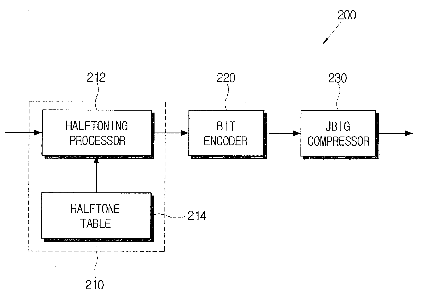
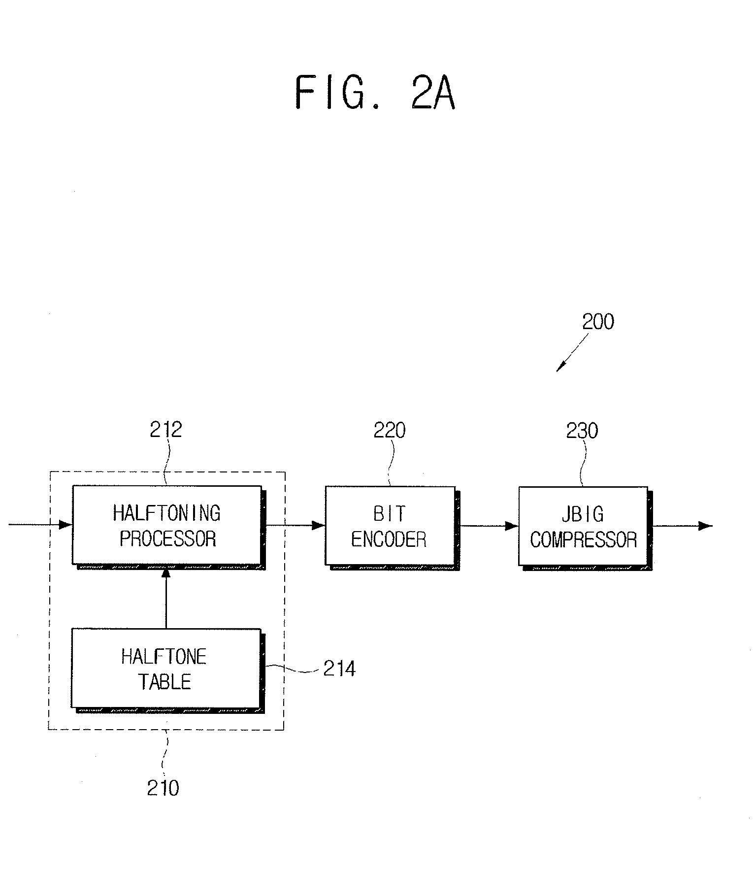
[0064]FIGS. 2A and 2B are control block diagrams illustrating configurations of two different parts of an image forming apparatus according to an embodiment of the present general inventive concept. FIG. 2A is a control block diagram illustrating a configuration of a sending side of an image forming apparatus, such as a computer. FIG. 2B is a control block diagram illustrating a configuration of a receiving side of an image forming apparatus such as a printer. The sending side illustrated in FIG. 2A and the receiving side illustrated in FIG. 2B may both be included in a single image forming apparatus.

[0065]As illustrated in FIG....


PUM


Abstract

An image forming apparatus, including a halftone image converter to convert input image data having a plurality of bits per pixel into halftone image data having a binary pixel value corresponding to a bright pixel or a dark pixel, and a bit encoder to divide the halftone image data into blocks with a predetermined size, and to perform a bit-encoding operation by using the number of either the bright or dark pixels in the block to output encoded image data.

Description

CROSS-REFERENCE TO RELATED APPLICATIONS[0001]This application claims priority under 35 U.S.C. § 119(a) from Korean Patent Application No. 2006-0105898, filed on Oct. 30, 2006, in the Korean Intellectual Property Office, the disclosure of which is incorporated herein in its entirety by reference.BACKGROUND OF THE INVENTION[0002]1. Field of the Invention[0003]The present general inventive concept relates to an image forming apparatus and an image forming method thereof, and more particularly, to an image forming apparatus which improves a printing speed by reducing a transmission size of halftone image data and enhances spatial resolution, and an image forming method thereof.[0004]2. Description of the Related Art[0005]A performance quality of an image forming apparatus such as a laser printer and a multifunction printer can be determined by printing quality and printing speed. Factors to determine the printing speed, which is measured in units known as page per minute (PPM), include ...

Claims


Application Information

Patent Timeline
IPC IPC(8): G06F15/00
CPCH04N1/4105H04N1/405H04N1/413G06F3/1215
Inventor LEE, HAE-KEELEE, HO-KEUNKIM, CHOON-WOOJEE, JONG-OKRYU, BYONG-TAE
Owner SAMSUNG ELECTRONICS CO LTD
Why Eureka
Try Eureka