
Communication Apparatus, Communication System and Communication Method

Active Publication Date: 2008-05-01
PANASONIC INTELLECTUAL PROPERTY CORP OF AMERICA
View PDF2 Cites 6 Cited by
  • Summary
  • Abstract
  • Description
  • Claims
  • Application Information

AI Technical Summary

Benefits of technology

[0010]The present invention makes it possible to prevent traffic increase in the public network and increase in communication cost in the public network, by redoing function allocation to apparatuses.

Problems solved by technology

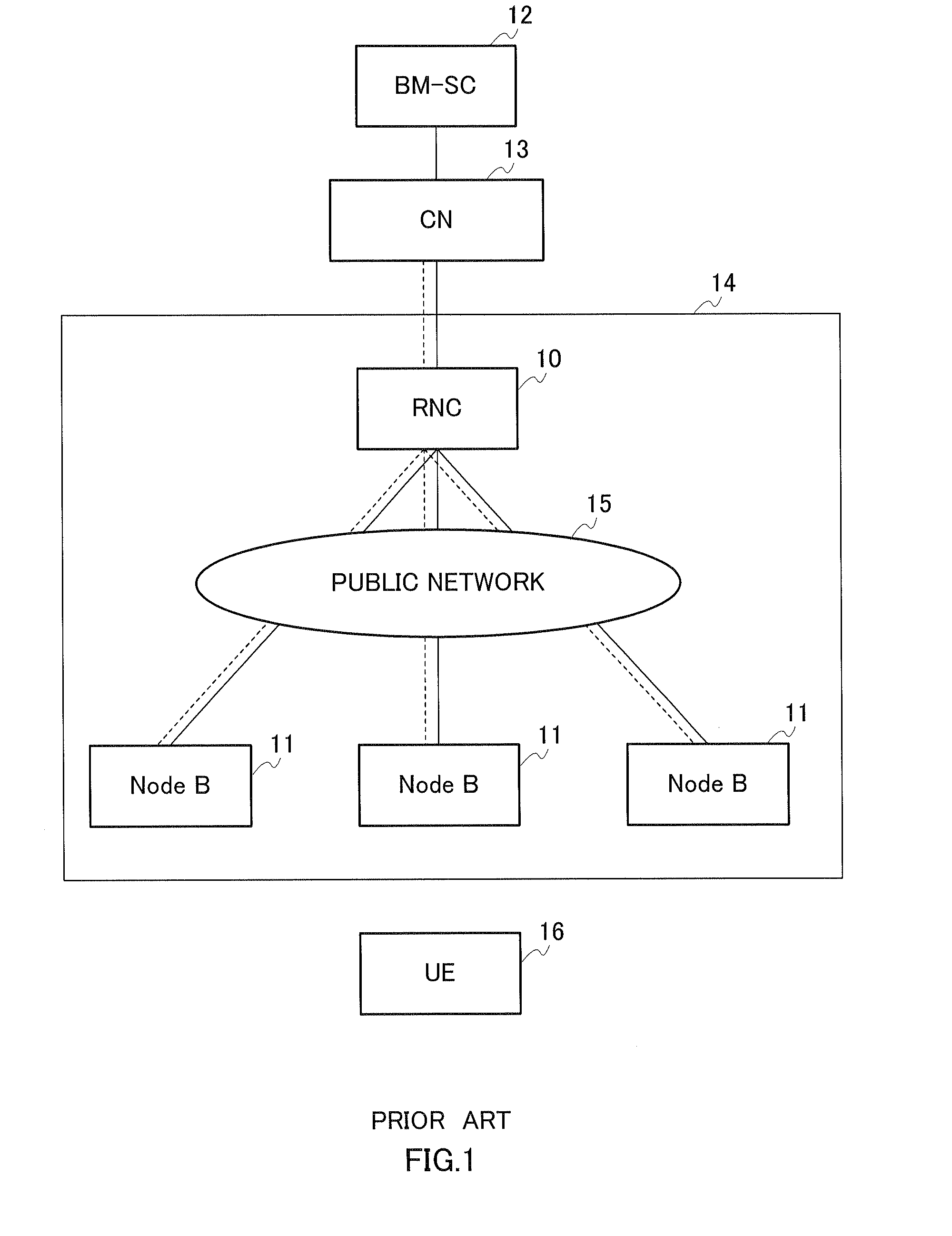
However, conventionally, there is a problem that since MBMS data of the same content duplicated by the RNC is transmitted by using the public network, the traffic in the public network increases, and the communication cost of the public network increases.

Method used


Image

  • Communication Apparatus, Communication System and Communication Method
  • Communication Apparatus, Communication System and Communication Method
  • Communication Apparatus, Communication System and Communication Method

Examples


embodiment 1

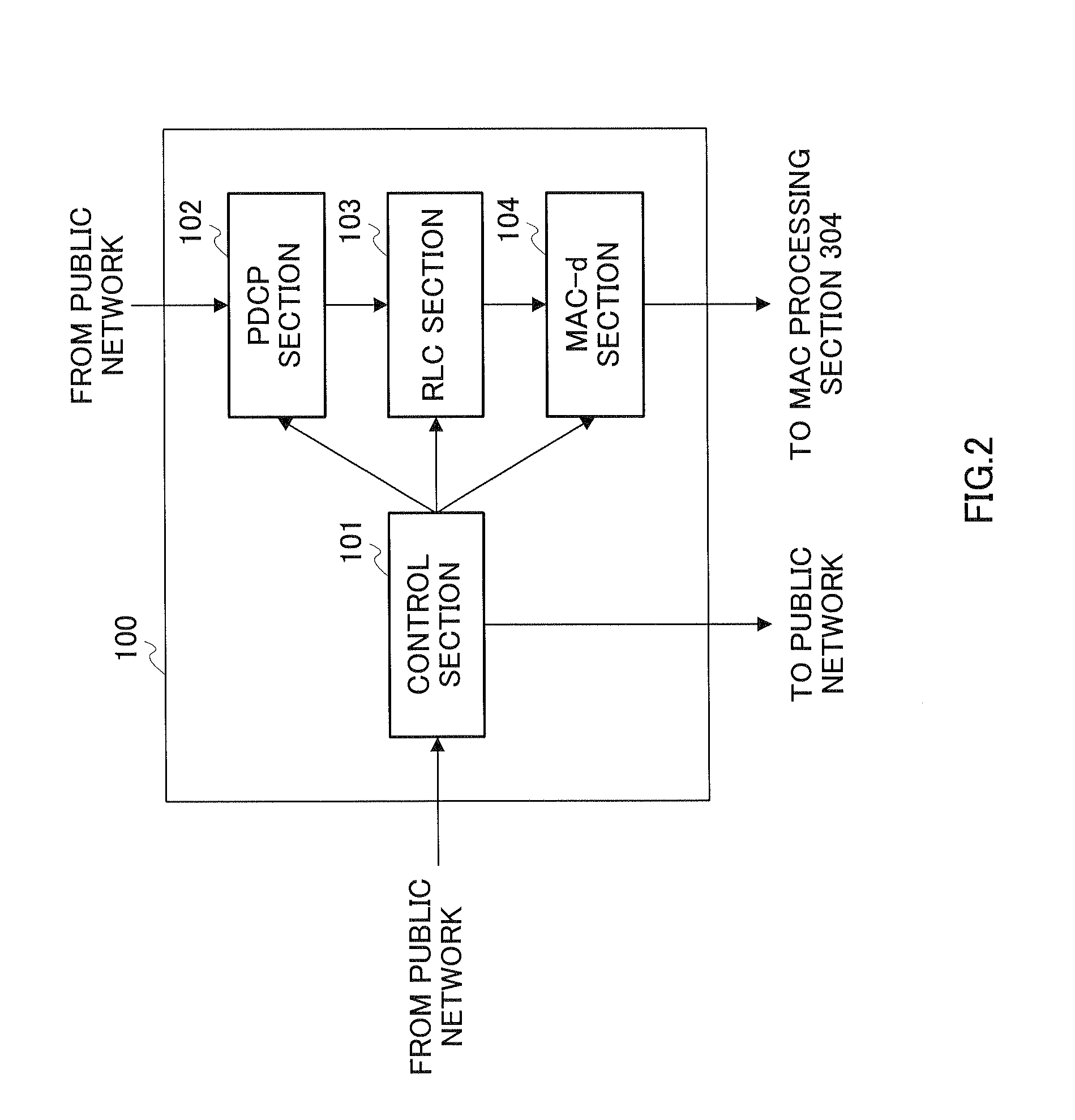
[0020]FIG. 2 is a block diagram showing a configuration of RNC-u 100, which is a communication apparatus according to embodiment 1 of the present invention. In embodiment 1 of the present invention, RNC which is an upper station apparatus, is divided into an RNC-c (first upper station apparatus) to which mainly the C-plane functions of the RNC are allocated, and an RNC-u (second upper station apparatus) to which mainly the U-plane functions of the RNC are allocated. RNC-u 100 in FIG. 2 are allocated mainly the U-plane functions of the RNC.

[0021]Control section 101 carries out control between RNC-u 100 and an RNC-c (described later). Specifically, control section 101 controls PDCP section 102, RLC section 103 and MAC-d section 104, based on control signals and information about the radio resource control result received from the RNC-c and received via the public network. Also, when control section 101 receives a notice regarding duplication of MBMS data from RNC-c, control section 10...

embodiment 2

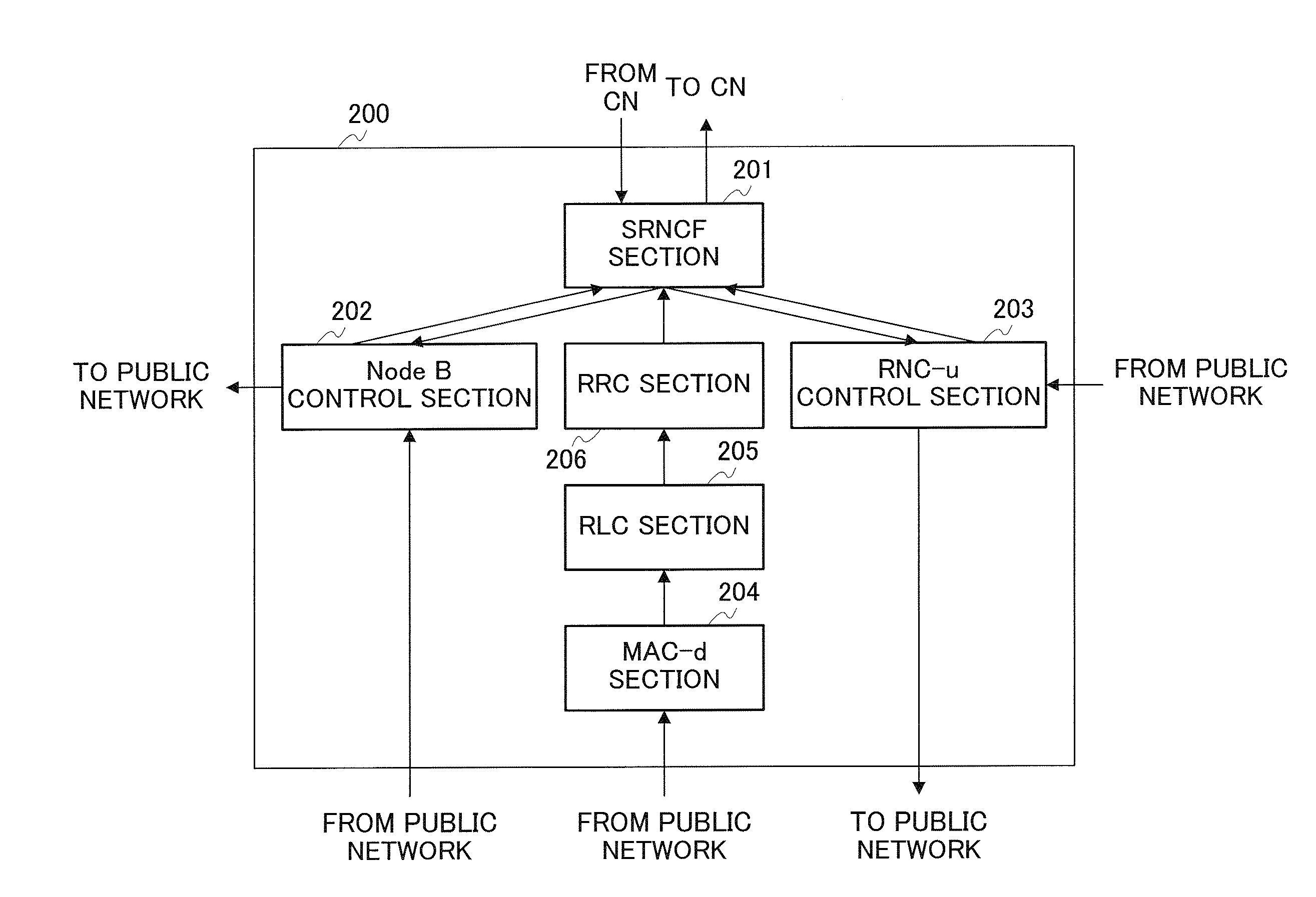
[0066]FIG. 8 is a sequence diagram showing the operation of RNC-u 100, RNC-c 200, Node B 300 and UE 400. The circle symbols of FIG. 8 show that the messages pass through the nodes. In embodiment 2, since the configuration of RNC-u 100 is the same as that shown in FIG. 2, the configuration of RNC-c 200 is the same as that shown in FIG. 3, the configuration of Node B 300 is the same as that shown in FIG. 4, and the configuration of UE 400 is the same as that shown in FIG. 5, description thereof is hereby omitted. Also, parts in FIG. 8, having the same operation as those shown in FIG. 7 are assigned the same reference numeral, and further description thereof is hereby omitted.

[0067]RNC-c 200, which has received a “RRC connection request” at Node B control section 202, transmits a “radio link setup request” from Node B control section 202 to Node B 300, via a public network, to set up a radio link for RRC connection (step ST603).

[0068]Next, control section 301 of Node B 300 selects RNC-...


PUM


Abstract

A communication apparatus wherein the function arrangement of each device is revised, thereby preventing an increase in traffic of a public network and further suppressing an increase in communication cost of the public network. In this apparatus, a control part (101), when notified of a duplication of MBMS data by RNC-c, controls a PDCP part (102), an RLC part (103) and a MAC-d part (104) so as to perform an MBMS data duplication process. The control part (101), when notified of an establishment of a communication line with a node (B), controls the PDCP part (102), RLC part (103) and MAC-d part (104) so as to establish the communication line with the node (B). The RLC part (103) duplicates, based on the control by the control part (101), the MBMS data received from the PDCP part (102). The MAC-d part (104) transmits the MBMS data as MAC processed to the node (B) via a local network between an RNC-u (100) and the node (B).

Description

TECHNICAL FIELD[0001]The present invention relates to a communication apparatus, communication system and communication method. More particularly, the present invention relates to a communication apparatus, communication system and communication method that provide multicast packet communication services.BACKGROUND ART[0002]FIG. 1 is a view showing the configuration of a packet communication system that provides multicast packet communication services (Multimedia Broadcast / Multicast Services) (hereinafter referred to as “MBMS”). In MBMS, control station apparatus (hereinafter referred to as “RNC”) 10 duplicates MBMS data and transfers the result to base station apparatuses (hereinafter referred to as “Node B”) 11. In FIG. 1, the solid line shows the signal flow in the user plane (hereinafter referred to as “U-plane”), and the dotted line shows the signal flow in the control plane (hereinafter referred to as “C-plane”).[0003]Service center (Broadcast / Multicast Service Center) (herein...

Claims


Application Information

Patent Timeline
IPC IPC(8): H04L1/00H04L12/70
CPCH04L12/189H04W4/06H04W88/12H04W28/10H04W28/08
Inventor FUKUI, AKITOIIDA, KENICHIROKANAZAWA, TAKESHITAMURA, TOMOFUMI
Owner PANASONIC INTELLECTUAL PROPERTY CORP OF AMERICA
Learn More