Spatial sparsity induced temporal prediction for video compression

a temporal prediction and spatial sparsity technology, applied in the field of compression/decompression, can solve the problems of affecting performance, limited prior solutions, and limited generic motion compensation prediction operation

Active Publication Date: 2008-05-01
NTT DOCOMO INC
View PDF8 Cites 20 Cited by
  • Summary
  • Abstract
  • Description
  • Claims
  • Application Information

AI Technical Summary

Problems solved by technology

There are a number of drawbacks of related art solutions.
For example, some prior solutions are limited to taking advantage of very specific types of temporal dependencies among video frames.
That is, the generic motion compensated prediction operation is limited to forming predictors for the current frame by using blocks from previously decoded frames directly, or by using low-pass filter based interpolations of these blocks.
For example, low pass filtered versions of blocks undergoing such variations can remove relevant high frequency signal components from the prediction and actually hurt performance.
These unaccounted variations cause serious performance penalties as they produce motion compensated differentials that are very difficult to code with the transform coders employed in hybrid video coders.
However, these solutions are not valid beyond the specific problems for which they are designed.
Hence, they do not provide general and robust solutions.
Also, some researchers have also devised frame adaptive motion interpolation filters but these too are limited to very specific temporal evolution models.
Furthermore, because one can only have a limited number of filtering possibilities, the effectiveness of such designs is very limited over video sequences that show scenes rich with spatial frequencies.
Related art typically proceeds with a piecewise smooth frame model under uniform translational motion assumptions and runs into problems whenever actual coded frames deviate from these assumptions.

Method used


Image

  • Spatial sparsity induced temporal prediction for video compression
  • Spatial sparsity induced temporal prediction for video compression
  • Spatial sparsity induced temporal prediction for video compression

Examples


Embodiment Construction

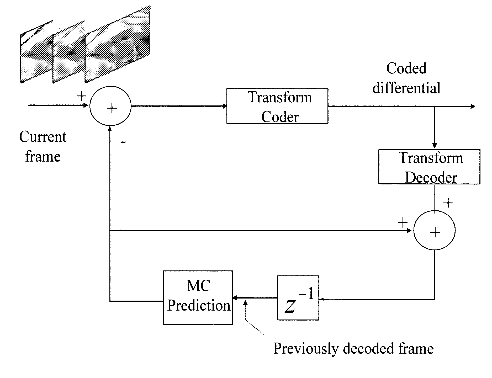
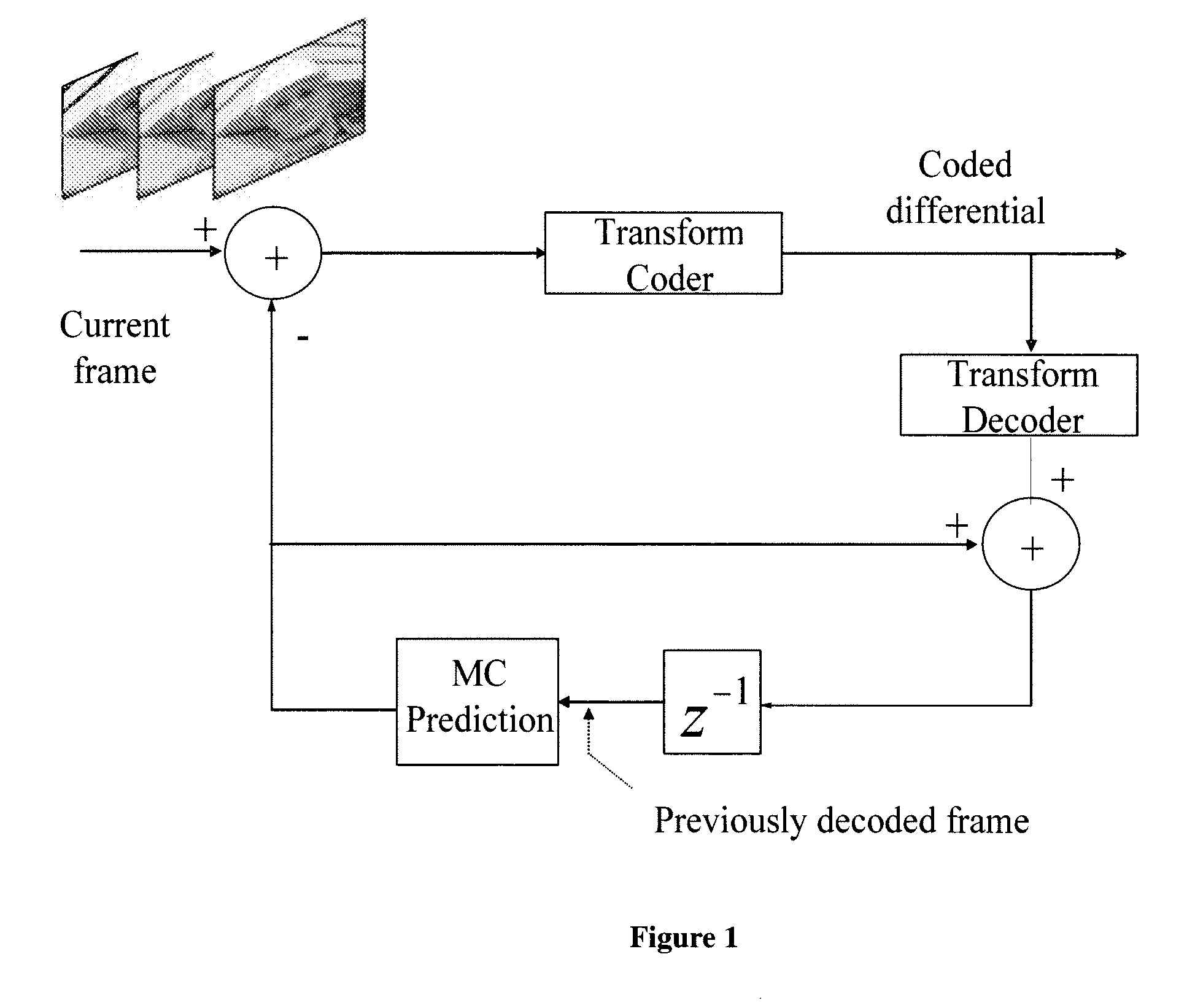
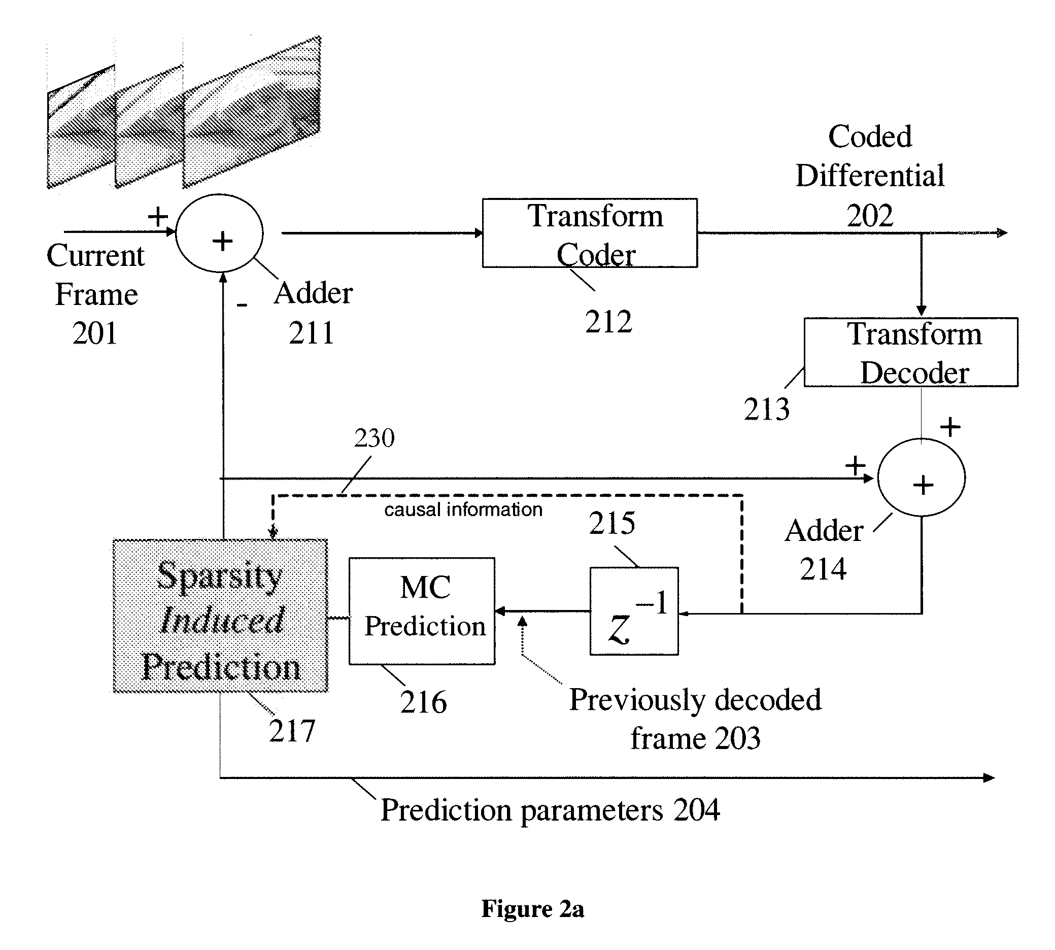
[0025] Methods and apparatuses for improved motion compensated prediction of video frames are described. In one embodiment, the method is designed to form an automatic and successful prediction (in the mean squared error sense, for example) during sophisticated temporal evolutions encountered in video sequences. In one embodiment, the method forms a prediction of the frame to be coded based on one or more previously decoded frames.

[0026] The technique described herein can operate successfully in many scenarios where traditional motion compensated prediction fails or does not perform well. For example, when temporally uncorrelated white noise is present in video frames and prediction of the frame to be coded will benefit from the removal of the noise in the previously decoded frame, in one embodiment, the method automatically accomplishes denoising of the previously decoded frame during motion compensated prediction. Also, in one embodiment, when blending of several scenes is presen...


PUM


Abstract

A method and apparatus are disclosed herein for spatial sparsity induced temporal prediction. In one embodiment, the method comprises: performing motion compensation to generate a first motion compensated prediction using a first block from a previously coded frame; generating a second motion compensated prediction for a second block to be coded from the first motion compensated prediction using a plurality of predictions in the spatial domain, including generating each of the plurality of predictions by generating block transform coefficients for the first block using a transform, generating predicted transform coefficients of the second block to be coded using the block transform coefficients, and performing an inverse transform on the predicted transform coefficients to create the second motion compensated prediction in the pixel domain; subtracting the second motion compensated prediction from a block in a current frame to produce a residual frame; and coding the residual frame.

Description

PRIORITY [0001] The present patent application claims priority to and incorporates by reference the corresponding provisional patent application Ser. No. 60 / 856,048, titled, “Spatial Sparsity Induced Temporal Prediction for Video Compression,” filed on Oct. 31, 2006. RELATED APPLICATIONS [0002] This application is related to U.S. patent application Ser. No. 11 / 471,741, entitled “A Nonlinear, Prediction Filter for Hybrid Video Compression,” filed on Jun. 20, 2006, assigned to the corporate assignee of the present invention.FIELD OF THE INVENTION [0003] The present invention relates to the field of compression / decompression; more particularly, the present invention relates to generating predictions in the transform domain for use in motion compensation as part of compression and decompression. BACKGROUND OF THE INVENTION [0004] Hybrid video compression consists of encoding an anchor video frame and then predictively encoding a set of predicted frames. Predictive encoding uses motion c...

Claims


Application Information

Patent Timeline
Patent Type & Authority Applications(United States)
IPC IPC(8): H04N7/50
CPCH04N19/197H04N19/105H04N19/46H04N19/51H04N19/196H04N19/583H04N19/117H04N19/137H04N19/18H04N19/48H04N19/82H04N19/61H04N19/60
Inventor GULERYUZ, ONUR G.HUA, GANG
Owner NTT DOCOMO INC
Why Eureka
Try Eureka