

High helix/low lead cutting tool
a cutting tool and high helix technology, applied in the field of rotary milling cutters, can solve the problem of difficult task of manufacturing ibr's
- Summary
- Abstract
- Description
- Claims
- Application Information
AI Technical Summary
Benefits of technology
Problems solved by technology
Method used
Image

Examples
Embodiment Construction
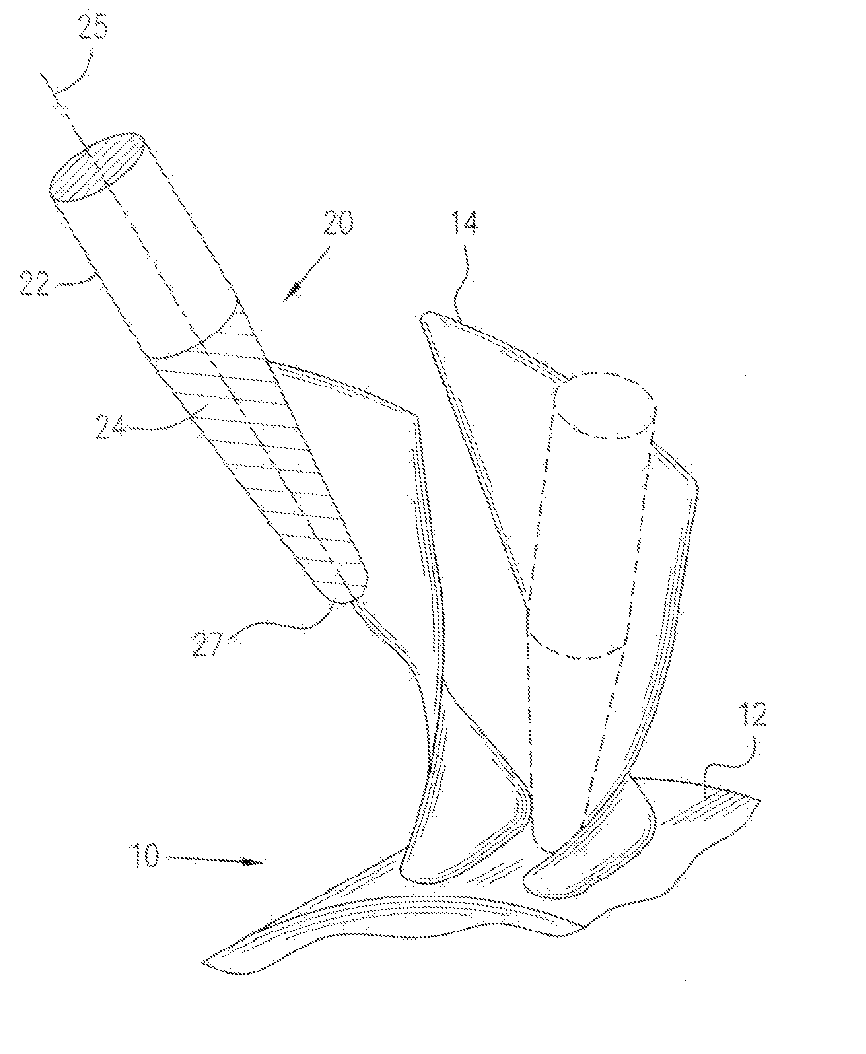
[0014]FIG. 1 schematically illustrates a milling cutter of the present invention generally indicated by numeral 20, used, for example, for machining an Integrally Bladed Rotor (IBR) generally indicated by numeral 10, of a gas turbine engine. IBR 10 comprises a hub 12 and a plurality of integral airfoils 14 projecting substantially radially outwardly therefrom. Manufacturing IBR's is a challenging task not only due to the complex geometry of airfoil surfaces, but also due to the material such as titanium or nickel alloys of which IBR's are usually made.
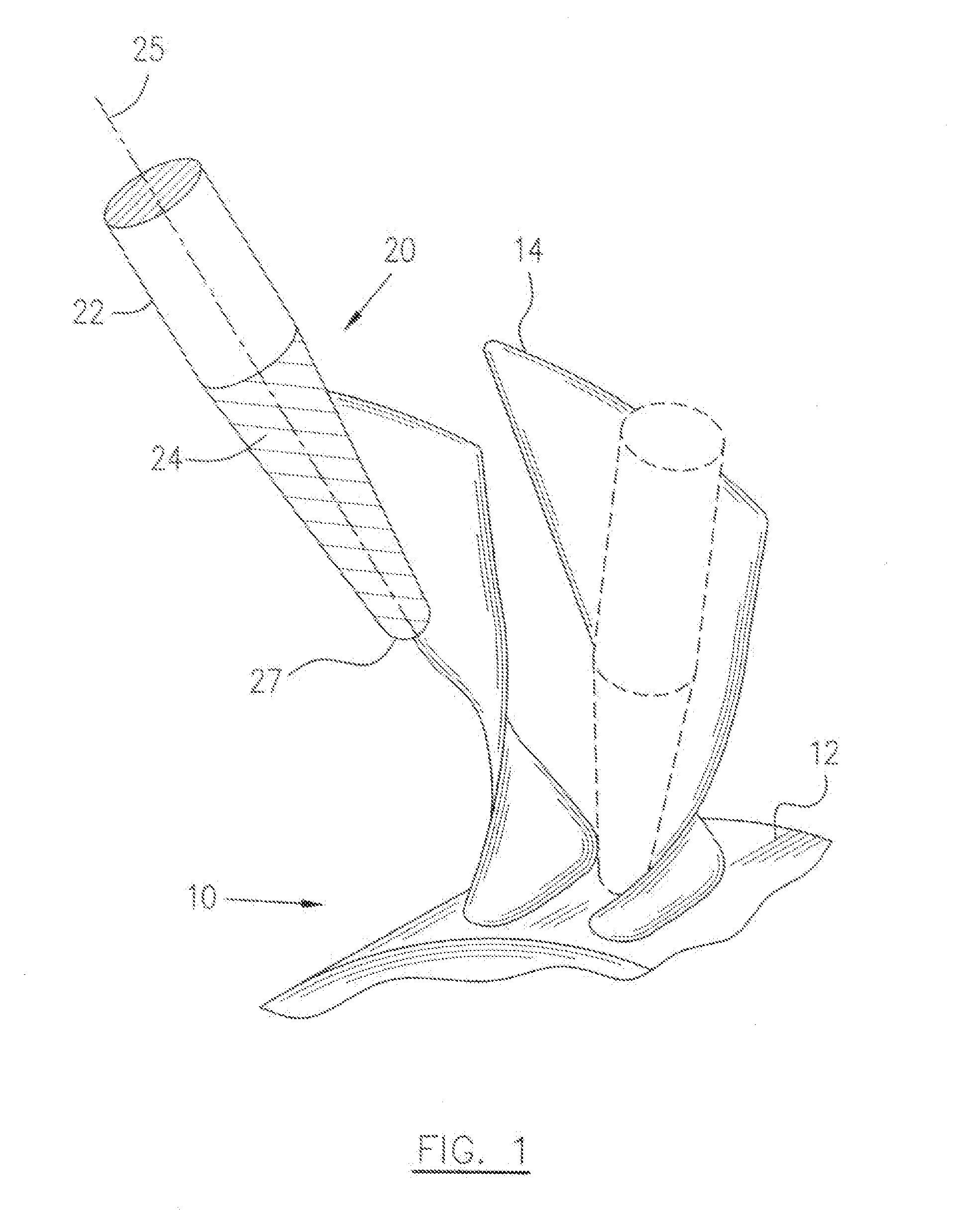
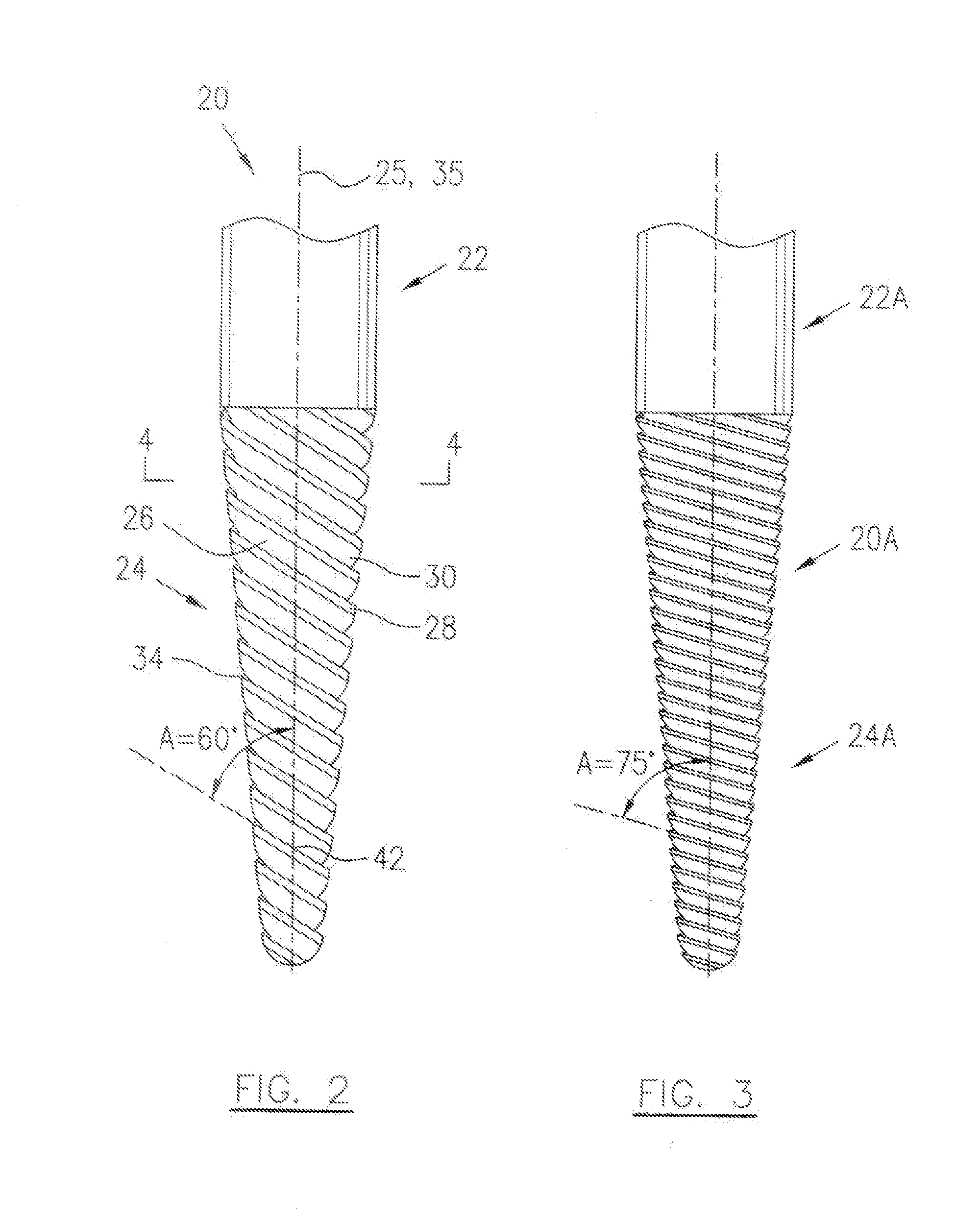
[0015]The milling cutter 20 according to one embodiment of the present invention generally includes a shank section 22 which is preferably substantially cylindrical, joined to a cutting section 24. The milling cutter 20 is adapted to be mounted to a spindle of a milling machine (not shown) to rotate about a longitudinal axis 25 of the shank section 22. The longitudinal axis 25 is also the longitudinal axis of the milling cutter 20 duri...
PUM
| Property | Measurement | Unit |
|---|---|---|
| helix angle | aaaaa | aaaaa |
| helix angle | aaaaa | aaaaa |
| helix angle | aaaaa | aaaaa |
Abstract
Description
Claims
Application Information