Revision Fixation Plate and Method of Use

a fixation plate and plate body technology, applied in the field of fixation system, can solve the problems of spinal cord or nerve compression, overgrowth of joint and ligamentous tissue, and instability of the spine,

Active Publication Date: 2008-05-01
WARSAW ORTHOPEDIC INC
View PDF8 Cites 58 Cited by
  • Summary
  • Abstract
  • Description
  • Claims
  • Application Information

AI Technical Summary

Benefits of technology

[0011] In another aspect, a system is provided for extending a first, implanted spinal fixation element to one or more adjacent vertebrae while leaving the first, implanted spinal fixation element in place. A flexible elongated extension member extends from the implanted spinal fixation element to at least one additional vertebra.
[0012] In another embodiment, a system is provided for extending a first, implanted spinal fixation element to one or more adjacent vertebrae. The system includes a first flexible coupler and a second flexible coupler positioned at a coupling end portion of an elongated extension member.
[0013] There is also disclosed a system for extending a first, implanted spinal fixation element to one or more additional adjacent vertebrae while leaving the first, implanted spinal fixation element in place, which includes a flexible elongated extension member having a longitudinal axis extending between a coupling end portion and a bone engagement end portion. The flexible elongated extension member may have a length between the coupling end portion and the bone engagement portion to extend from said first, implanted spinal fixation element to at least one additional vertebra. A first fastener to position said coupling end portion on the first, implanted spinal fixation element, and a second fastener locking the coupling end portion to the first fastener are also provided. The elongated extension member can be made of plastic, such as polyetheretherketone or polyketone. The flexible elongated extension member can be configured to provide a dynamic relationship between the first, implanted spinal fixation element and the additional vertebra(e). A washer can be provided configured to position the coupling end portion on the first, implanted spinal fixation element.
[0014] A system for extending a first, implanted spinal fixation element having a bone fastener attached to one or more additional vertebrae while leaving the bone fastener in place could include an elongated extension member having a longitudinal axis extending between a coupling end portion and a bone engagement end portion, the elongated extension member having a length between the coupling end portion and the bone engagement portion to extend from the first, implanted spinal fixation element to at least one additional vertebra. A first fastener to position the coupling end portion on the first, implanted spinal fixation element is included, as well as a first flexible coupler positioned between the first, implanted spinal fixation element and the bone fastener and a second flexible coupler positioned between the coupling end portion and the first, implanted spinal fixation element. Either or both flexible coupl...

Problems solved by technology

The spine may be unstable due to a traumatic injury, surgery, or invasion and destruction of the vertebrae by tumor.
Continued motion of particular segments of the spine may cause overgrowth of joint and ligamentous tissue which, in turn, may compress the spinal cord or...

Method used


Image

  • Revision Fixation Plate and Method of Use
  • Revision Fixation Plate and Method of Use
  • Revision Fixation Plate and Method of Use

Examples


Embodiment Construction

[0039] For the purposes of promoting an understanding of the principles of the invention, reference will now be made to the embodiments, or examples, illustrated in the drawings and specific language will be used to describe the same. It will nevertheless be understood that no limitation of the scope of the invention is thereby intended. Any alterations and further modifications in the described embodiments, and any further applications of the principles of the invention as described herein, are contemplated as would normally occur to one skilled in the art to which the invention relates.

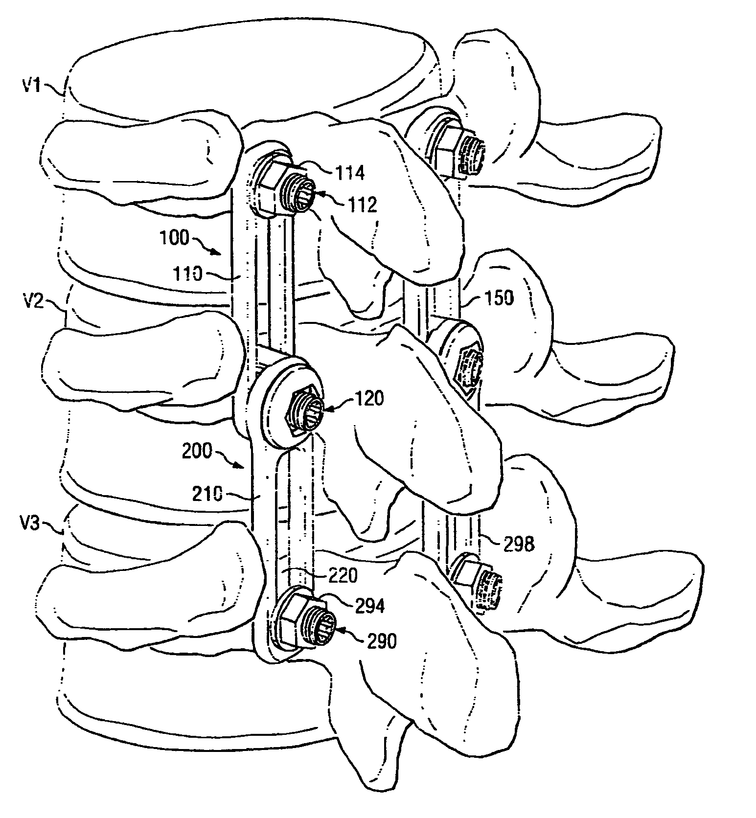
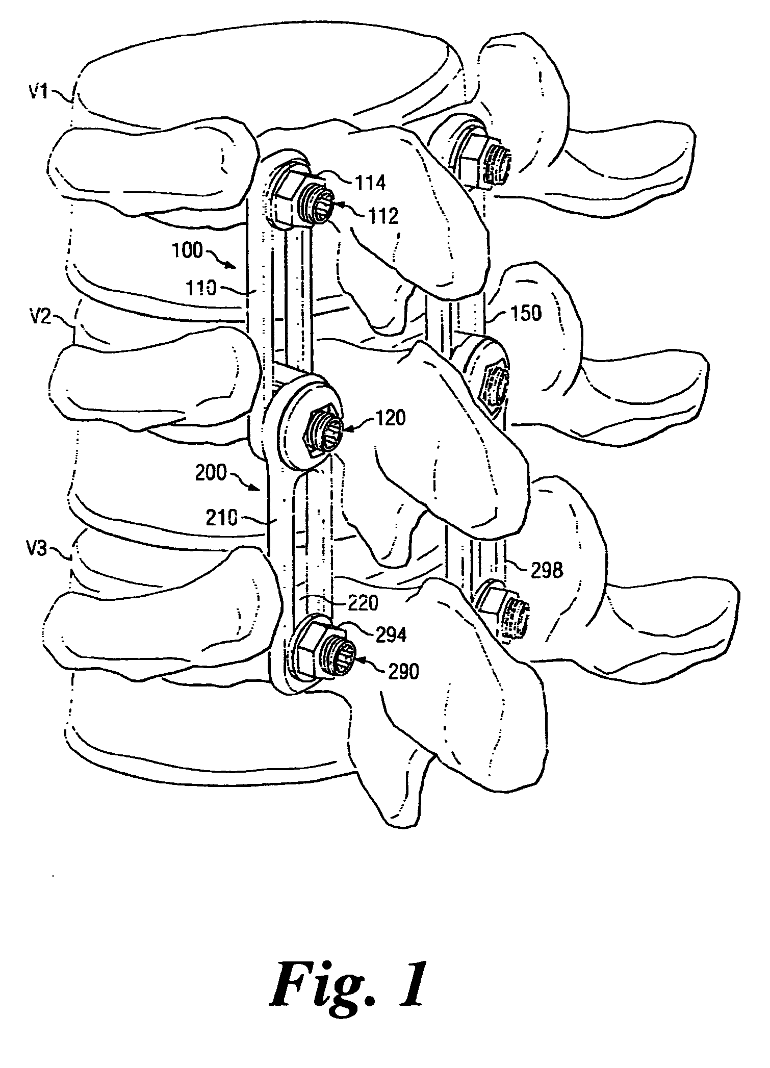
[0040] Spinal fixation systems, such as rod / screw systems and plate / screw systems, are often used to at least partially stabilize the spine to reduce movement between adjacent vertebrae. In some patients, there is a need to address continued degradation of the spine near the previously implanted spinal fixation system. In these circumstances, it is desirable to have a revision fixation system that ...


PUM


Abstract

A connection system is provided that joins a revision fixation plate to a previously implanted skeletal fixation plate. In one form, the system allows the previously implanted plating system to be revised without disturbing the original implant components. In one aspect, the connection includes joining the revision fixation plate to a previously implanted fastener. In another aspect, the revision fixation plate is directly joined to a previously implanted fixation plate. In yet another aspect, the connection includes forming a dynamic relationship between the previously implanted plating system, the revision fixation plate, and the affected vertebrae. In one form, the dynamic relationship enables movement between the previously implanted plating system and the affected vertebrae and in another form, the dynamic relationship enables movement between the previously implanted plating system and the revision fixation plate.

Description

[0001] This application is a Continuation-In-Part of U.S. patent application Ser. No. 11 / 411,751 filed Apr. 26, 2006 (Attorney Docket No. P0025734.00), which is hereby incorporated by reference.[0002] The present application relates generally to a fixation system for the treatment of the skeletal system. More particularly, the present invention may be applied to treatment of the human spine. [0003] Spinal fusion is performed to prevent motion between mobile segments of the spine. A variety of reasons exist for performing spinal fusion. The spine may be unstable due to a traumatic injury, surgery, or invasion and destruction of the vertebrae by tumor. Continued motion of particular segments of the spine may cause overgrowth of joint and ligamentous tissue which, in turn, may compress the spinal cord or its nerves. The curvature of the spine may become abnormal and cause deformity or neurological problems. In these instances, it may be desirable to prevent spinal motion at the affecte...

Claims


Application Information

Patent Timeline
IPC IPC(8): A61B17/58A61B17/08
CPCA61B17/7007A61B17/7001
Inventor CAPOTE, MARCOBRANCH, CHARLES L. JR.BISCUP, ROBERT S.
Owner WARSAW ORTHOPEDIC INC
Why Eureka
Try Eureka