Implant for placing in a blood circulation conduit

a technology of blood circulation and conduits, applied in blood vessels, prostheses, medical science, etc., can solve problems such as cardiac failure, valve calcification, and disease affecting valves

Inactive Publication Date: 2008-05-01
CORMOVE
View PDF10 Cites 122 Cited by
  • Summary
  • Abstract
  • Description
  • Claims
  • Application Information

AI Technical Summary

Benefits of technology

[0011] An object of the invention is to obtain an implantable endovalve as a replacement for a native valve, the obturator of which operates reliably and tightly for a long period of time, whatever the morphology of the patient.

Problems solved by technology

However, diseases affect the valves.
In particular, the valves can suffer from calcification which allows a reflux or a regurgitation toward the ventricle which expelled the blood flow.
The problem of regurgitation leads to abnormal dilation of the ventricle which ultimately leads to cardiac failure.
Endovalves are not completely satisfactory in some cases.
The obturator and its lamellae cannot operate reliably and satisfactorily for a long period of time if they are partially deformed.
Consequently, the obturator deteriorates rapidly, necessitating replacement of the endovalve.

Method used


Image

  • Implant for placing in a blood circulation conduit
  • Implant for placing in a blood circulation conduit
  • Implant for placing in a blood circulation conduit

Examples


Embodiment Construction

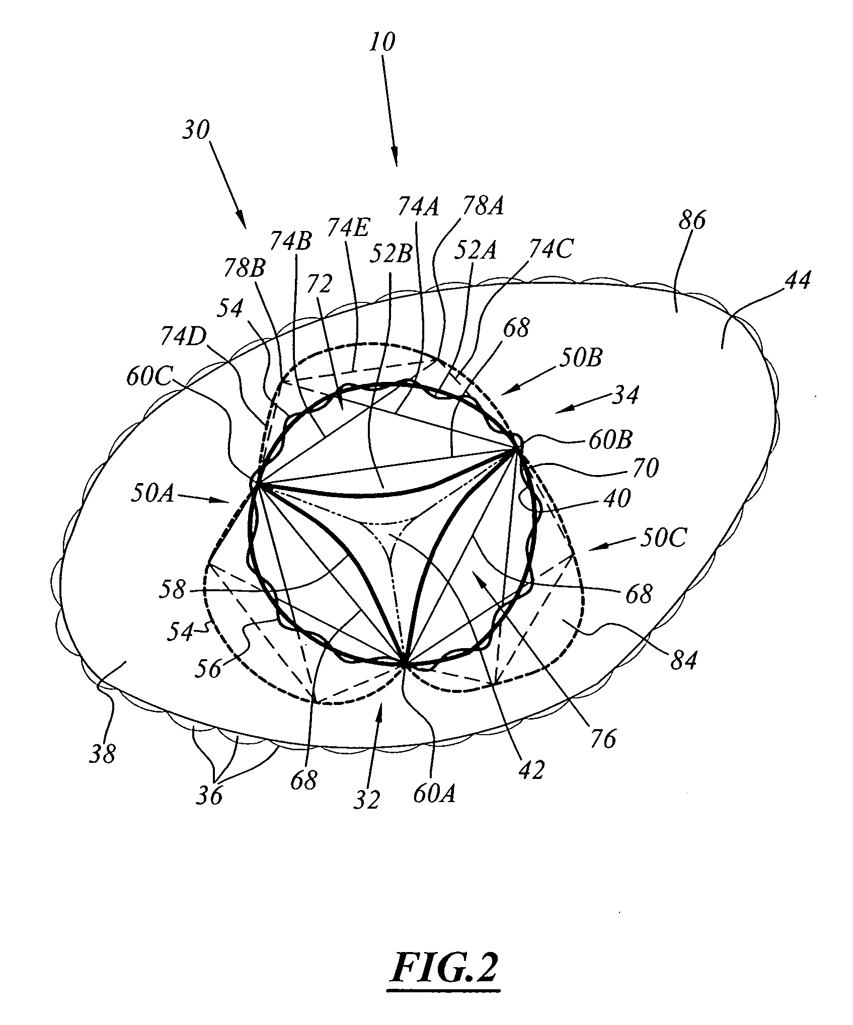
[0030] A first implant 10 according to the invention is shown in FIG. 1 to 4. This implant 10 is an endovalve for replacing a deficient native valve 12 shown in FIG. 3 in the coronary sinus 14.

[0031] The coronary sinus 14 is defined inside a wall having a narrow part 16 defining a blood circulation opening 18 and a flared region 20 in which the coronary arteries 22 open. The narrow part 16 forms the seat of the native valve 12.

[0032] The native valve 12 comprises lamellae 24 having a lower edge 26 articulated to the narrow part 16 and a free upper edge 28 extending in the sinus 14 opposite the flared wall 20.

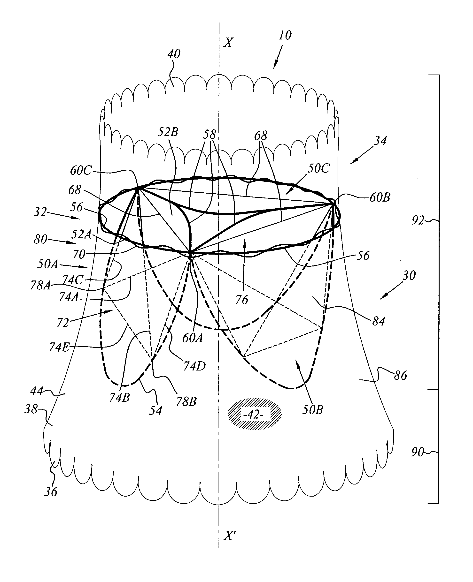
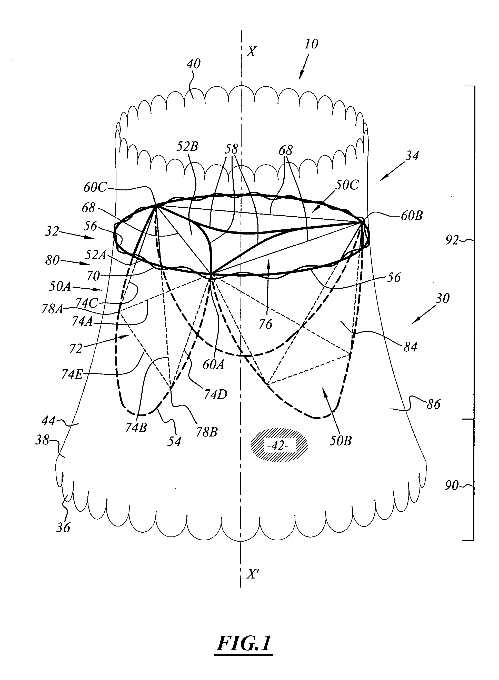
[0033] Referring to FIG. 1, the implant 10 comprises a radially deployable support endoprosthesis 30 and a flexible obturator 32 which is permanently fixed in the endoprosthesis 30.

[0034] According to the invention, the implant 10 further comprises a unit 34 for controlling the deployment of the endoprosthesis 30 in the region carrying the obturator 32.

[0035] The endoprosth...


PUM


Abstract

This implant (10) comprises a hollow body (30) adapted to be deployed between a compressed configuration and a totally dilated configuration constituting its rest configuration. The hollow body (30) has an internal surface (40) with an axis (X-X′) which delimits a blood circulation passage (42). The implant (10) comprises at least a constricting flexible threadlike link (68) which is linked to the hollow body at at least two linking points (60A, 60B, 60C) which are spaced angularly round the axis (X-X′) on its internal surface (40). The link (68) can be deployed between a retracted state and a deployed state during deployment of the hollow body (30). The distance separating the linking points (60A, 60B, 60C) in the deployed state of the threadlike link (68) is smaller than the distance separating these points (60A, 60B, 60C) in the totally dilated configuration of the hollow body (30) in the absence of threadlike link (68).

Description

TECHNICAL FIELD [0001] The present invention relates to an implant for placing in a blood circulation conduit, of the type comprising a hollow body which can be deployed between a compressed configuration and a totally dilated configuration which constitutes its rest configuration, the hollow body having an internal surface with an axis X-X′ delimiting a blood circulation passage. [0002] The invention applies, in particular, to the endovalves formed by a flexible obturator fitted in a tubular endoprosthesis and intended to replace a native cardiac valve. BACKGROUND TO THE INVENTION [0003] The heart comprises valves which are located at the outlet of the right ventricle (pulmonary valve) and of the left ventricle (aortic valve). [0004] These valves allow univocal circulation of the blood flow, preventing a reflux of blood following the ventricular contraction. [0005] However, diseases affect the valves. In particular, the valves can suffer from calcification which allows a reflux or ...

Claims


Application Information

Patent Timeline
Patent Type & Authority Applications(United States)
IPC IPC(8): A61F2/06A61F2/24
CPCA61F2230/0067A61F2/2418
Inventor STYRC, MIKOLAJPEROUSE, ERIC
Owner CORMOVE
Why Eureka
Try Eureka