Compression spring operated squirrel proof bird feeder

a compression spring and bird feeder technology, applied in the field of improved bird feeders, can solve the problems of insufficient design, lack of squirrel proof capability of general purpose bird feeders, etc., and achieve the effect of long-lasting operation and use, and convenient manufacturing

Active Publication Date: 2008-05-08
WOODSTREAM CORP
View PDF14 Cites 43 Cited by
  • Summary
  • Abstract
  • Description
  • Claims
  • Application Information

AI Technical Summary

Benefits of technology

[0012]A generally vertical compression spring is operatively connected between the inner housing and the outer housing to urge the outer housing toward its upper position in mating relation with the inner housing. The compression spring is also selected so as not to be overcome by a predetermined weight, such as the weight of an average or typical bird (or of several such birds), but readily overcome by the weight of an average or typical squirrel. Thus, the presence of a squirrel on the perch assembly will cause the outer housing to move to its lower position and close the through opening, thereby restricting access to the birdseed.
[0017]A further object of the present invention is to provide a squirrel-proof birdfeeder in accordance with the preceding objects in which the compression spring supported around the base of the spring socket is protected from contact with birdseed in the birdfeeder and other contaminants which might interfere with operation of the compression spring to bias the outer housing toward its upper mating position with the inner housing.
[0020]A final object to be recited herein is to provide a squirrel-proof birdfeeder in accordance with the preceding objects, which can be easily manufactured from readily available and known components for ease and economy of manufacture and which will be sturdy and long lasting in operation and use.

Problems solved by technology

As a general purpose bird feeder, however, such designs have proven inadequate.
Conversely, general purpose bird feeders have been found lacking with regard to their squirrel proof capability.

Method used


Image

  • Compression spring operated squirrel proof bird feeder
  • Compression spring operated squirrel proof bird feeder
  • Compression spring operated squirrel proof bird feeder

Examples


Embodiment Construction

[0031]Although only preferred embodiments of the invention are explained in detail, it is to be understood that the invention is not limited in its scope to the details of construction and arrangement of components set forth in the following description or illustrated in the drawings. The invention is capable of other embodiments and of being practiced or carried out in various ways.

[0032]Also, in describing the preferred embodiments, terminology will be resorted to for the sake of clarity. It is intended that each term contemplates its broadest meaning as understood by those skilled in the art, and includes all technical equivalents which operate in a similar manner to accomplish a similar purpose.

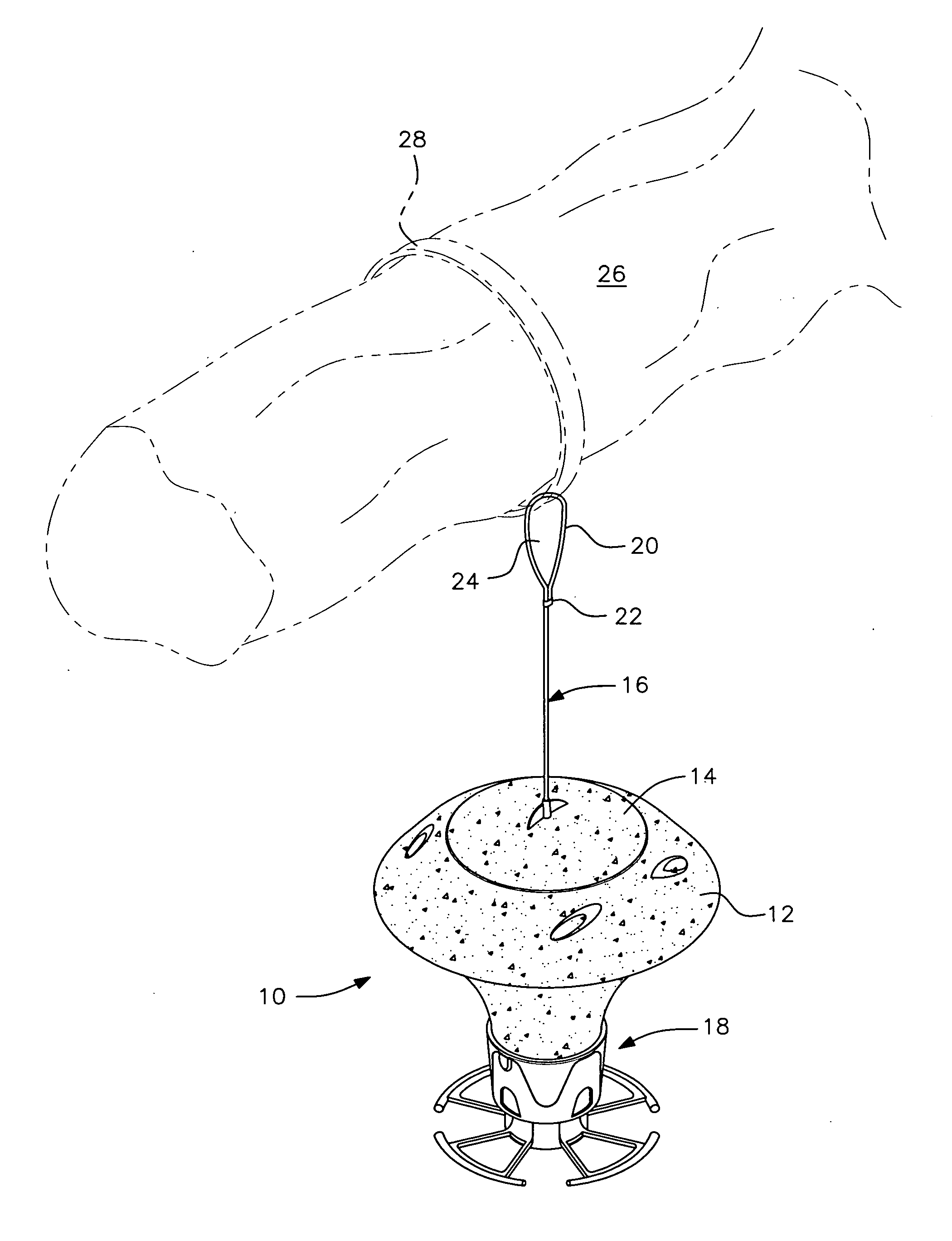
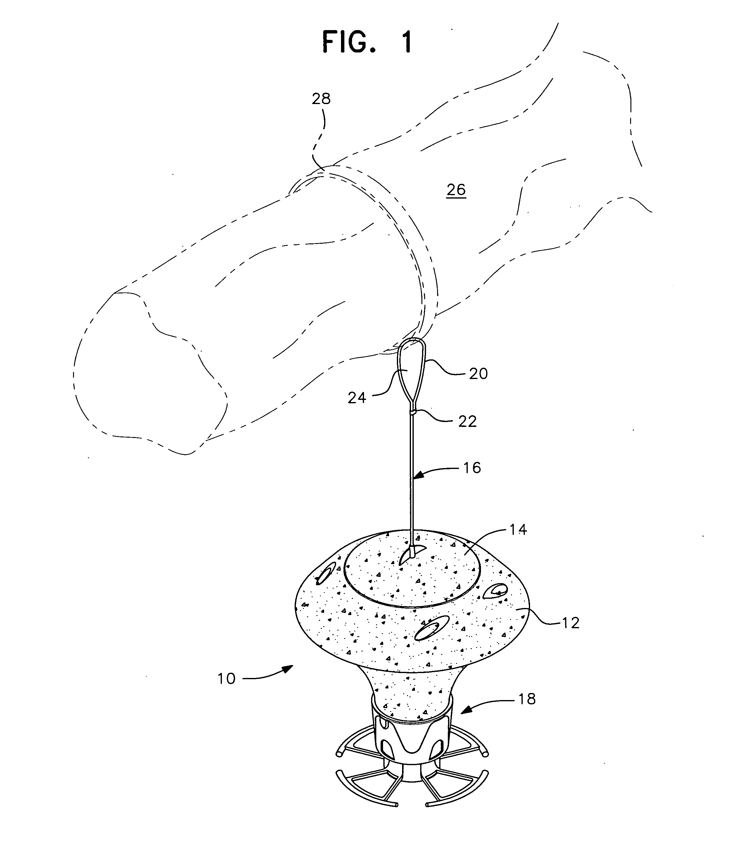
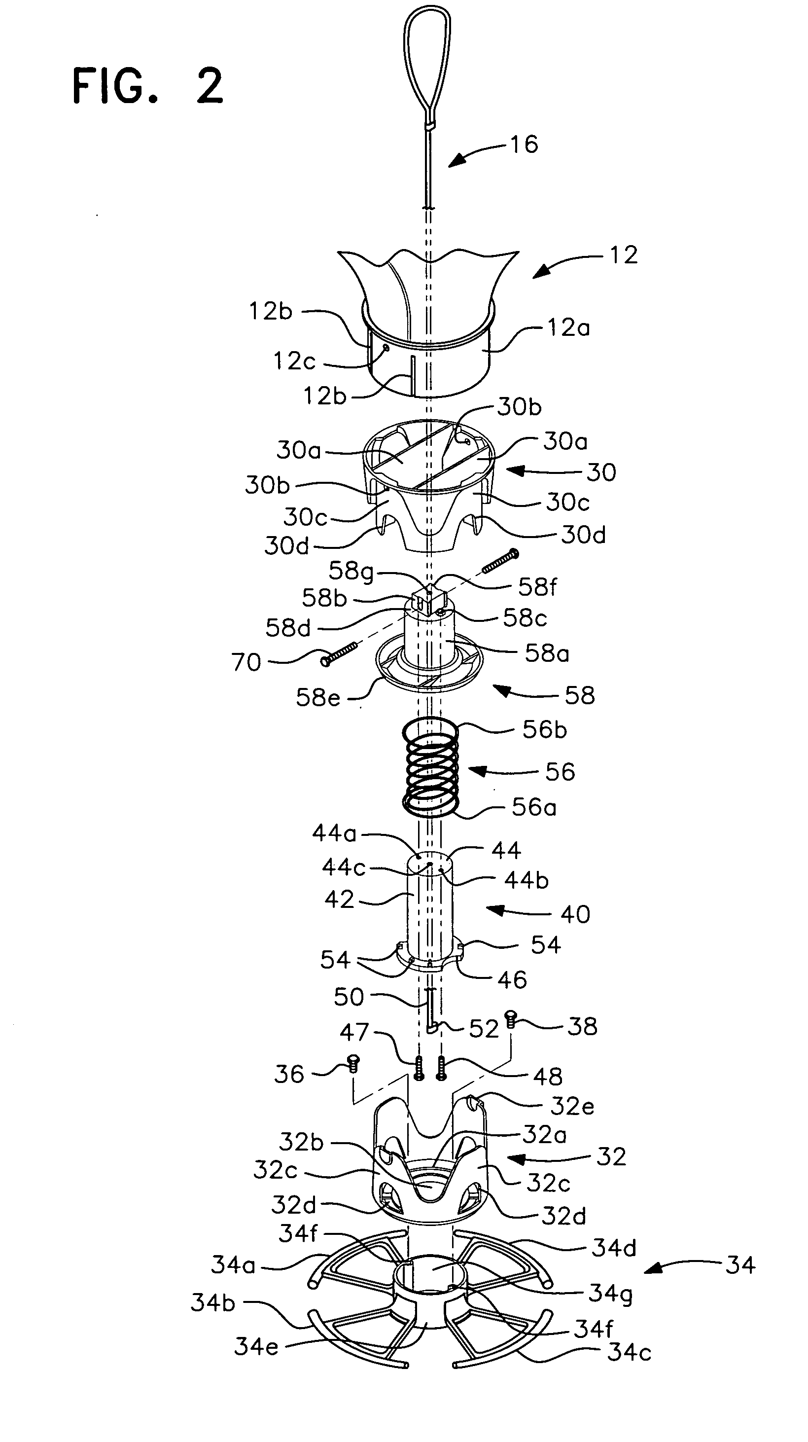
[0033]FIGS. 1 and 2 illustrate a compression spring operated squirrel proof bird feeder, generally designated by reference numeral 10, in accordance with a preferred embodiment of the present invention. The bird feeder 10 includes a birdseed storage container 12 having a removably mounted...


PUM


Abstract

A bird feeder has telescopically aligned inner and outer cylindrical housings with opposed surfaces of complementary shape that are reverse tapered in a substantially vertical direction to enable guided vertical movement of the housings with respect to each other. The housings have openings in their side walls which are substantially in alignment when the outer housing is in an upper position and misaligned when the outer housing is in a lower position. A compression spring centrally located about the vertical axis of the feeder is confined within a lower portion of the feeder and biases the outer housing to its upper position. When the outer housing is moved to its lower position by the weight of a squirrel overcoming the biasing force of the compression spring, the housing openings are substantially misaligned such that no significant through opening exists, thereby preventing access to the birdseed.

Description

BACKGROUND OF THE INVENTION[0001]1. Field of the Invention[0002]The present, invention is generally directed to an improved bird feeder of desirably simple and economic construction and, more specifically, to a bird feeder that is squirrel proof and that can be adapted to a wide variety of uses so as to be fairly characterized as a general purpose bird feeder.[0003]2. Description of the Prior Art[0004]There have been numerous attempts over the years to design a bird feeder that is squirrel proof. Certain of these feeders are designed for a specific purpose or installation and are relatively squirrel proof when so used. As a general purpose bird feeder, however, such designs have proven inadequate. Conversely, general purpose bird feeders have been found lacking with regard to their squirrel proof capability.[0005]The above-described problem is known in the prior art and several patents disclose feeders which accomplish the squirrel proof objective in ways different from each other a...

Claims


Application Information

Patent Timeline
Patent Type & Authority Applications(United States)
IPC IPC(8): A01K39/01
CPCA01K39/0113
Inventor RICH, CHRISTOPHER T.CRUZ, ROBERT T.HOLLIDAY, EDWARD J.
Owner WOODSTREAM CORP
Why Eureka
Try Eureka