
Safety cabinet

a safety cabinet and cabinet body technology, applied in the field of safety cabinets, can solve the problems of devices susceptible to being unlocked or damaged, users of the safety cabinet often neglect to lock up such materials, etc., and achieve the effects of improving the control of the safety cabinet, increasing the restrictions on access, and quick observation

Inactive Publication Date: 2008-05-08
JUSTRITE MFG
View PDF37 Cites 26 Cited by
  • Summary
  • Abstract
  • Description
  • Claims
  • Application Information

AI Technical Summary

Benefits of technology

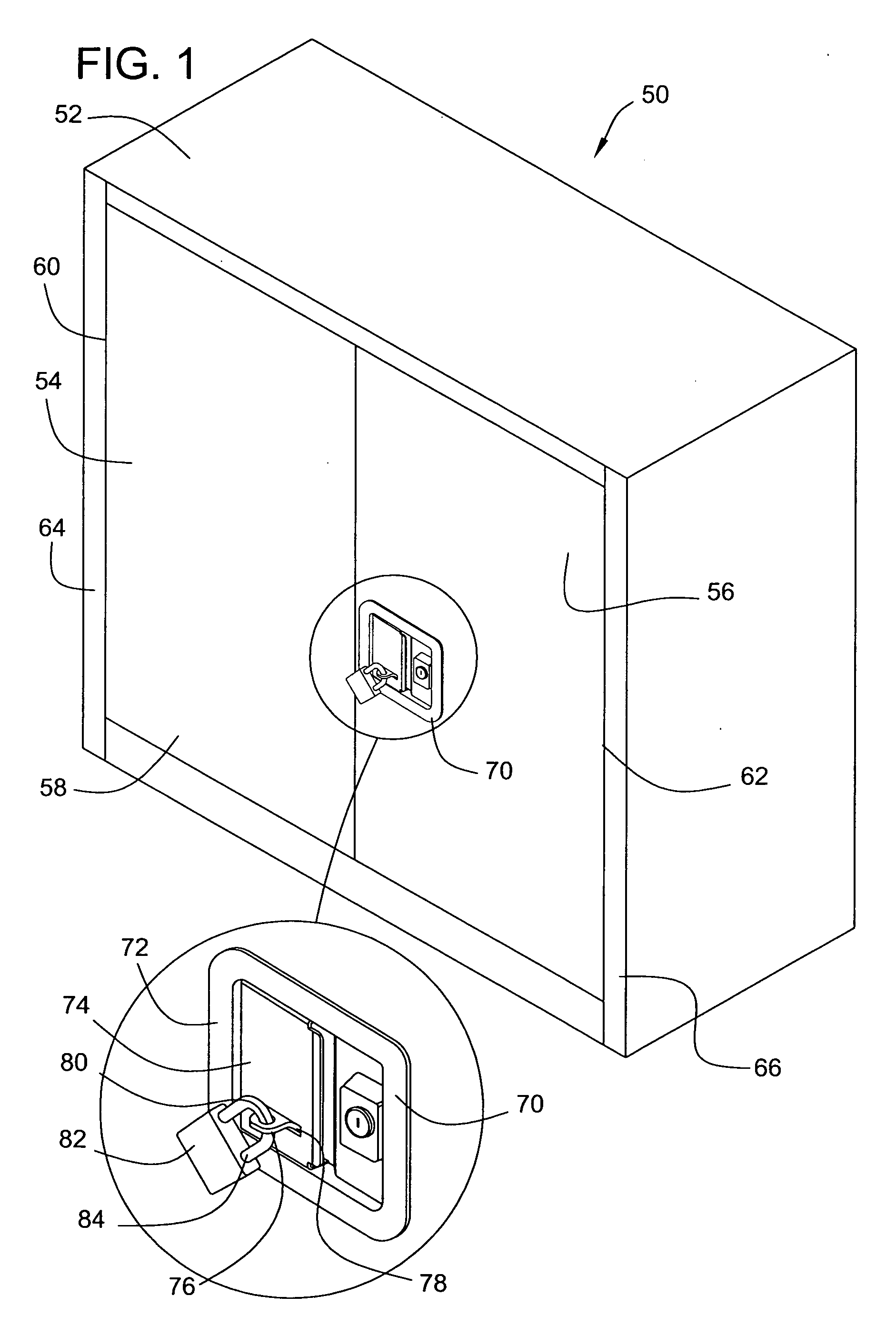
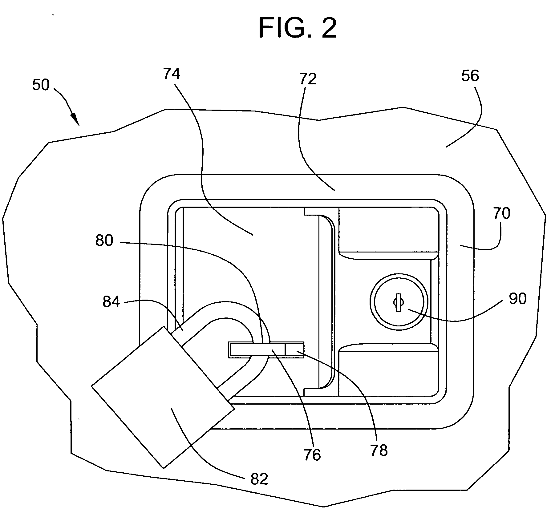
[0004]To provide improved control over a safety cabinet such that unauthorized personnel cannot access the safety cabinet, the present invention provides a safety cabinet including a paddle handle that can also be locked by a padlock. The padlock represents a robust, automatic locking system that is resistant to damage and to circumvention by tampering. The padlock can serve as second locking means that increases the restrictions on access to the safety cabinet. The padlock can also be clearly visible from outside the safety cabinet so that one can quickly observe whether the safety cabinet is locked or not.
[0005]In one embodiment, there is provided a safety cabinet comprising an enclosure defining an opening and a door rotatably attached to the enclosure. The door is movable between an open position and a closed position, the door configured to selectively cover the enclosure when in the closed position. The safety cabinet further comprises a latch system arranged with the door to selectively retain the door in the closed position. The latch system, in conjunction with an automatic door closure system, provides a simple and efficient way not only to latch the cabinet door but also to effectively selectively retain the door and the handle in a latched position.

Problems solved by technology

However, when a container of flammable material is stored in a lockable safety cabinet, users of the safety cabinet frequently neglect to lock up such material between uses.
Nonetheless, these devices are susceptible to being unlocked or damaged by unauthorized personnel who are able to defeat the locking means.

Method used


Image

  • Safety cabinet
  • Safety cabinet
  • Safety cabinet

Examples


Embodiment Construction

[0036]In the following description, reference is sometimes made to the “left,”“right”“top,”“bottom,” or other regions of the safety cabinet and its various components. It should be understood that these terms are used solely for convenient reference, inasmuch as the safety cabinet may be used omnidirectionally.

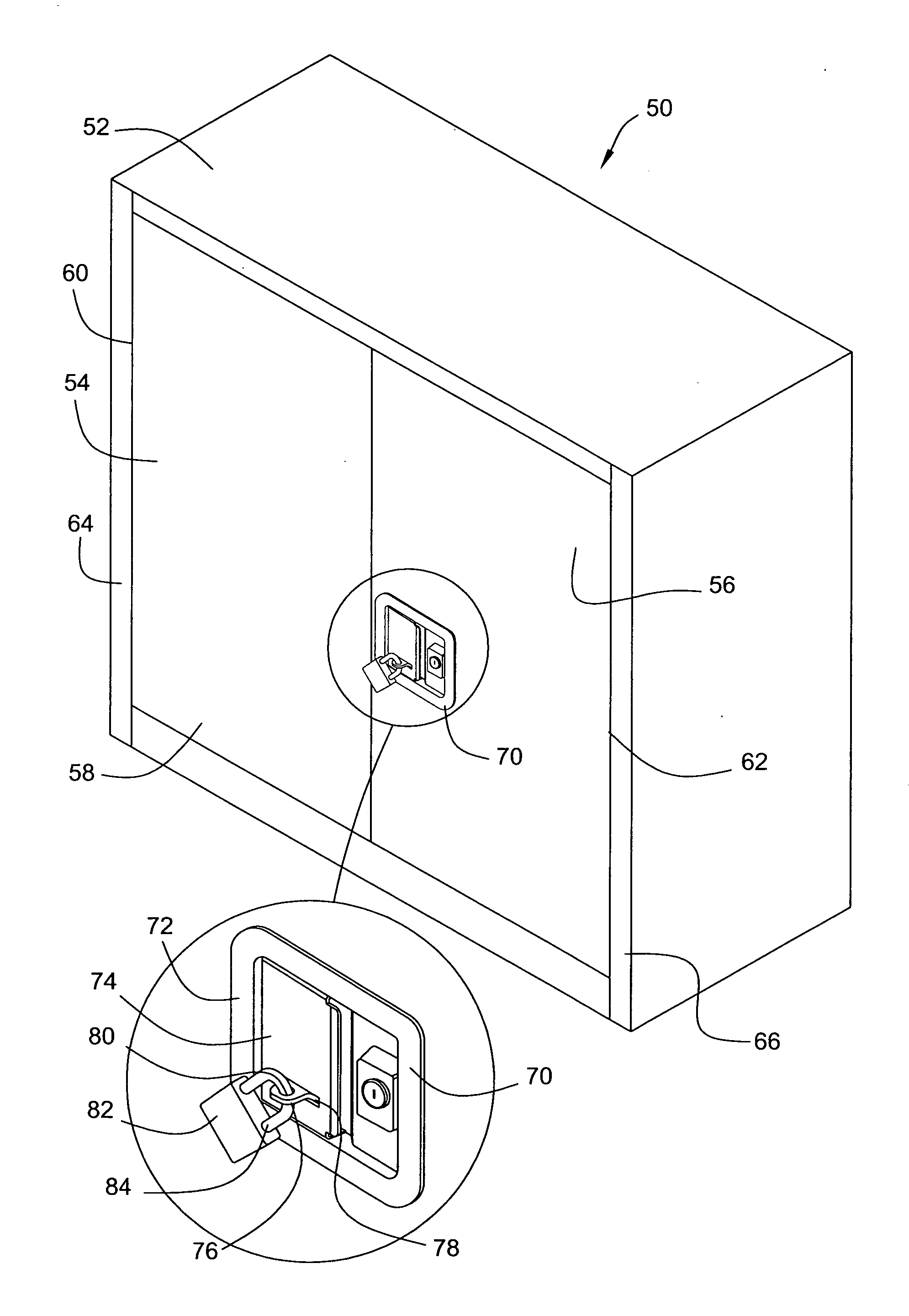
[0037]Turning now to the drawings, there is shown in FIG. 1 an illustrative fireproof safety cabinet 50 according to an embodiment of the present invention. The safety cabinet 50 can be similar in construction to a safety cabinet shown and described in U.S. Pat. No. 6,729,701 to Carter et al., which is herein incorporated by reference in its entirety. Systems and components of a safety cabinet not described in detail herein can be identical to the corresponding systems and components described in U.S. Pat. No. 6,729,701.

[0038]The safety cabinet includes an enclosure 52 having a left door 54 and a right door 56. The safety cabinet 50 can be used to store, for example, flammable...


PUM


Abstract

A safety cabinet comprises an enclosure defining an opening and a door rotatably attached to the enclosure. The door is movable between an open position and a closed position, the door configured to selectively cover the enclosure when in the closed position. The safety cabinet further comprises a latch system to selectively retain the door in the closed position. The latch system can include a paddle handle to operate the latch system. The paddle handle includes a housing, an operating lever to actuate the paddle handle, and a tang. The operating lever is movable between a normal position and an operating position. The tang passes through a slot in the operating lever when the operator lever is in the normal position with an opening in the tang being accessible for receiving a padlock therethrough. The tang is configured such that when a padlock passes through the opening of the tang, the padlock will prevent the operating lever from moving to the operating position.

Description

FIELD OF THE INVENTION[0001]The present invention pertains generally to a safety cabinet for flammable, combustible, or other hazardous materials. More particularly, the present invention relates to a safety cabinet having a door with a paddle handle configured to receive a padlock.BACKGROUND OF THE INVENTION[0002]A safety cabinet for storing flammable or explosive materials is known in the art. Such a safety cabinet located at a plant allows for the onsite storage of flammable material. The safety cabinet can be provided to insulate flammable material stored within it from the direct effects of an external fire to prevent the flammable material from adding to the deleterious effect of the original fire. Often, either according to law or to an internal standard operating procedure, the safety cabinet is equipped with a locking mechanism, which provides an added safety feature by preventing inadvertent, improper usage of the flammable material and by allowing access to the flammable ...

Claims


Application Information

Patent Timeline
Patent Type & Authority Applications(United States)
IPC IPC(8): E05B65/46
CPCE05B13/002E05B13/10E05C9/026E05B67/00E05C17/30E05B65/0075
Inventor MARCUS, GARY A.CARTER, GLEN A.
Owner JUSTRITE MFG
Learn More