Magnetic resonance imaging apparatus

a magnetic resonance imaging and apparatus technology, applied in the direction of magnetic variable regulation, process and machine control, instruments, etc., can solve the problems becoming a factor of reducing operation efficiency or safety,

Active Publication Date: 2008-05-08
TOSHIBA MEDICAL SYST CORP
View PDF20 Cites 17 Cited by
  • Summary
  • Abstract
  • Description
  • Claims
  • Application Information

AI Technical Summary

Benefits of technology

[0011]In view of such circumstances, preventing the cable from obstructing an operatio

Problems solved by technology

The cable in such a state obstructs, e.g., an operation of mounting the subject on the top panel, thereby becoming a factor of a reduction in an operation efficiency or safety.
When using the plurality of receiving coils on the gantr

Method used


Image

  • Magnetic resonance imaging apparatus
  • Magnetic resonance imaging apparatus
  • Magnetic resonance imaging apparatus

Examples


Embodiment Construction

[0035]A magnetic resonance imaging apparatus (an MRI apparatus) according to an embodiment will now be explained in detail hereinafter with reference to FIG. 1 to FIGS. 19A, 19B, and 19C. It is to be noted that like reference numerals denote like members in these drawings.

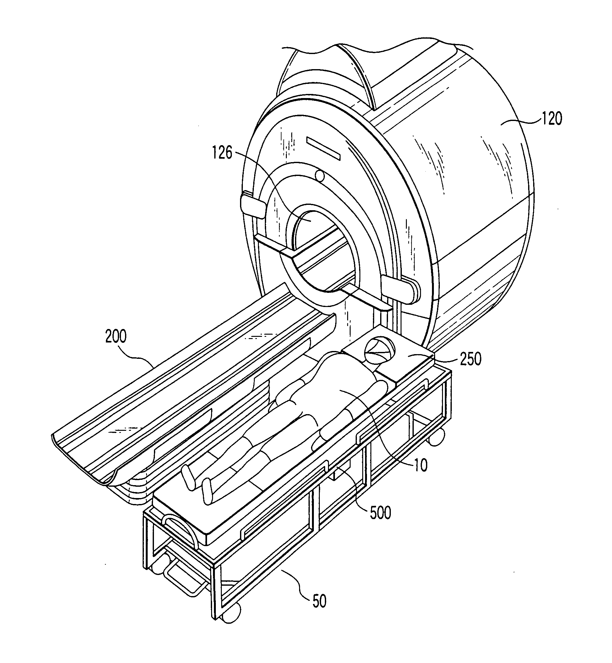
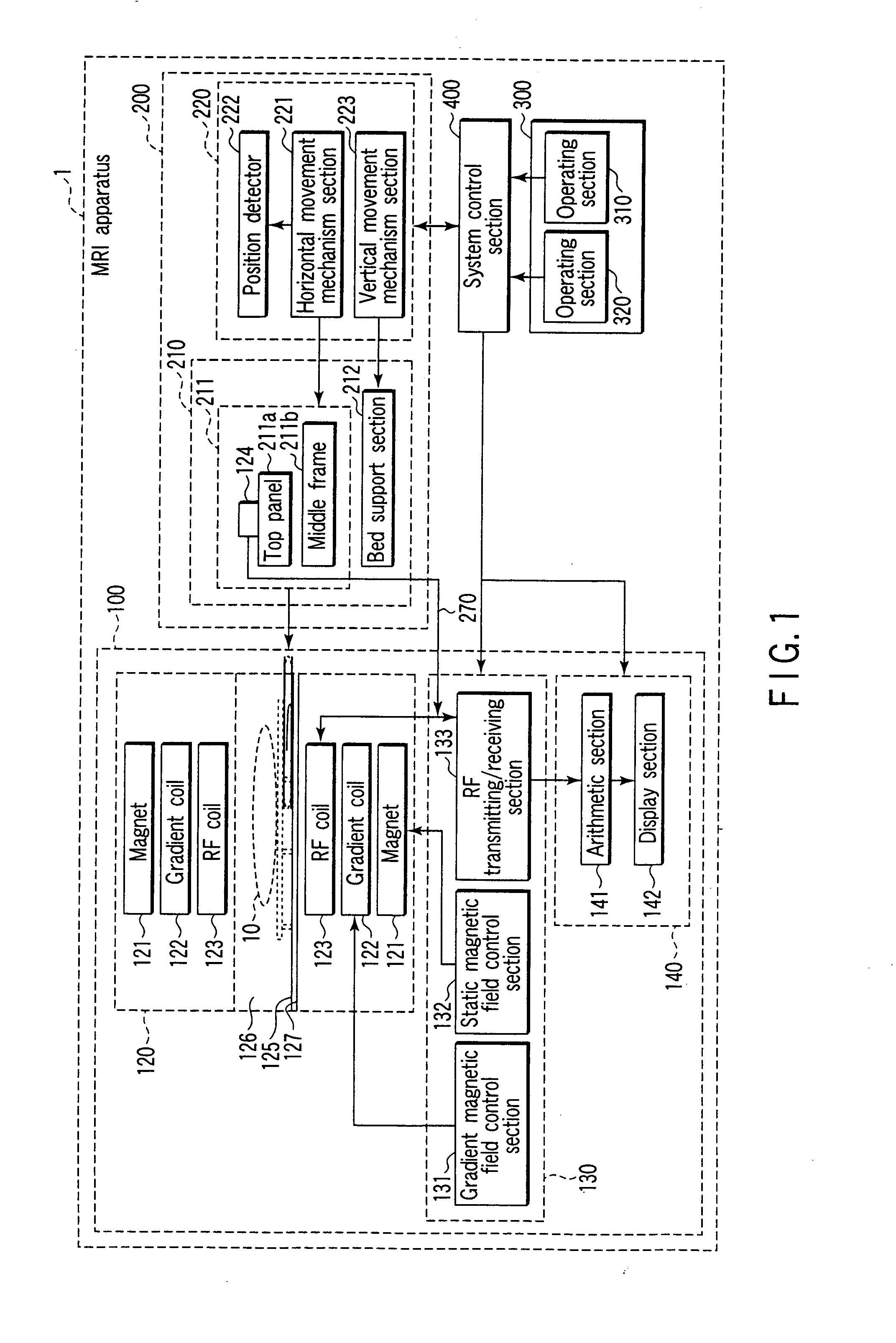
[0036]FIG. 1 is a block diagram showing a structure of an MIR apparatus 1 according to this embodiment. The MRI apparatus 1 includes an imaging section 100, a bed device 200, an operating section 300, and a system control section 400. The imaging section 100 collects a magnetic resonance signal (an MR signal) from a subject 10, and performs an arithmetic operation based on the collected MR signal. The bed device 200 sets the subject 10 at an imaging position of the imaging section 100. The operating section 300 accepts an operation by an operator to control the imaging section 100 and the bed device 200. The system control section 400 controls the imaging section 100 and the bed device 200 based on a signal from th...


PUM


Abstract

A magnetic resonance imaging apparatus includes a gantry having an imaging space therein, a receiving circuit that receives a magnetic resonance signal emitted from a subject arranged in the imaging space, and a bed device on which the subjected is mounted, wherein the bed device includes a top panel on which the subject is mounted, a bed support section which supports the top panel to enable moving the top panel in such a manner that the subject mounted on the top panel is positioned in the imaging space, connection ports provided on the top panel to connect signal transmission cables of RF coils which convert the magnetic resonance signal into an electric signal, and connecting unit which electrically connects the signal transmission cables with the receiving circuit through the inside of the bed support section.

Description

CROSS-REFERENCE TO RELATED APPLICATIONS[0001]This application is based upon and claims the benefit of priority from prior Japanese Patent Applications No. 2006-159599, filed Jun. 8, 2006; and No. 2007-138036, filed May 24, 2007, the entire contents of both of which are incorporated herein by reference.BACKGROUND OF THE INVENTION[0002]1. Field of the Invention[0003]The present invention relates to a magnetic resonance imaging apparatus that receives a magnetic resonance signal emitted from a subject by a receiving coil arranged on a top panel side on which the subjected is mounted.[0004]2. Description of the Related Art[0005]A magnetic resonance imaging apparatus generates image data about a subject based on a magnetic resonance signal (an MR signal) detected from the inside of the subject. More specifically, the magnetic resonance imaging apparatus reconstructs a magnetic resonance image (an MR image) concerning a subject arranged in a static magnetic field space based on an MR sign...

Claims


Application Information

Patent Timeline
IPC IPC(8): G01R33/28
CPCG01R33/34007G01R33/36G01R33/3415
Inventor OHSAWA, TAKUHIRO
Owner TOSHIBA MEDICAL SYST CORP
Why Eureka
Try Eureka