
Display system with digital signal processor unit and related display method

Active Publication Date: 2008-05-08
INNOLUX CORP +1
View PDF6 Cites 0 Cited by
  • Summary
  • Abstract
  • Description
  • Claims
  • Application Information

AI Technical Summary

Problems solved by technology

In such case, the display system 1 is unduly complicated and costly.

Method used


Image

  • Display system with digital signal processor unit and related display method
  • Display system with digital signal processor unit and related display method
  • Display system with digital signal processor unit and related display method

Examples


Embodiment Construction

[0012]Reference will now be made to the drawings to describe various embodiments of the present invention in detail. In the following description, unless the context indicates otherwise, a reference to a “signal” includes where appropriate a reference to a group of signals, and includes where appropriate a reference to data.

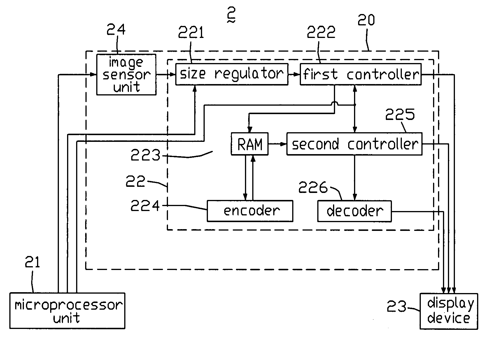
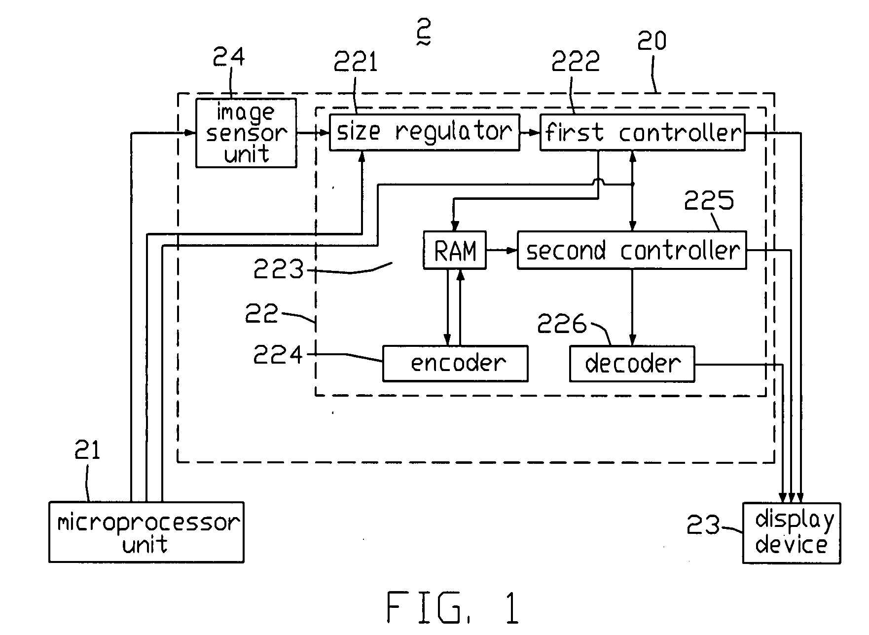
[0013]Referring to FIG. 1, a display system 2 according to an exemplary embodiment of the present invention is shown. The display system 2 includes an image sensor 20, a microprocessor unit 21, and a display device 23.

[0014]The image sensor 20 includes an image sensor unit 24 and a digital signal processor unit 22 integrated therein.

[0015]The image sensor unit 24 includes a number of photodiodes (not shown). When light irradiates each photodiode, a current is generated according to the intensity of the light.

[0016]The digital signal processor unit 22 includes a size regulator 221, a first controller 222, a second controller 225, a random access memory (RAM) 223, ...


PUM


Abstract

An exemplary display system (2) includes a display device (23), an image sensor (20), and a microprocessor unit (21). The image sensor includes an image sensor unit (24) and a digital signal processor unit (22) integrated therein. The image sensor unit is configured for generating a current. The digital signal processor includes a size regulator (221) configured for receiving the current, generating an analog image signal according to the current, and providing the analog image signal to the display device. The microprocessor unit is configured for initializing the image sensor unit.

Description

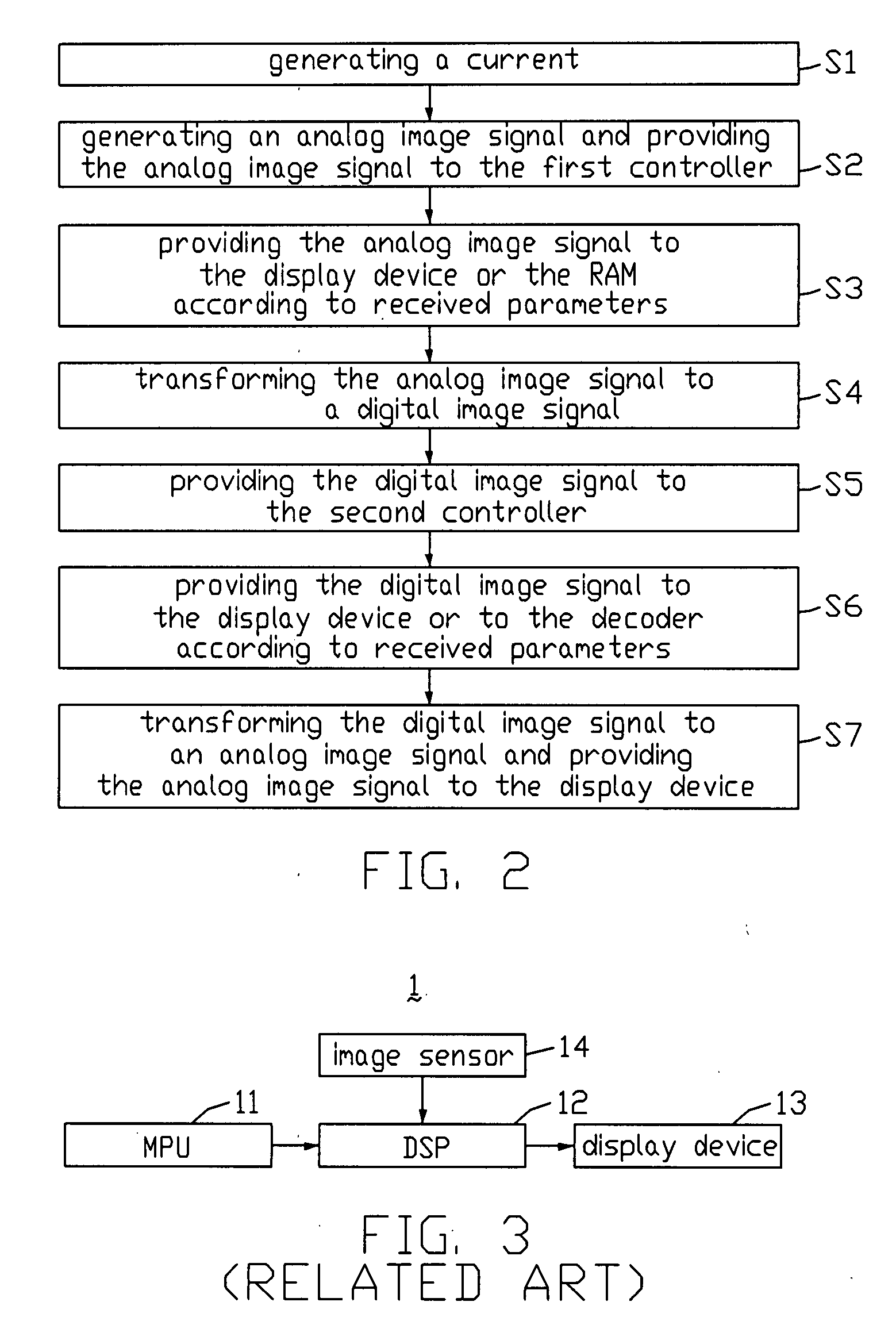
FIELD OF THE INVENTION[0001]The present invention relates to display systems and methods for displaying images on display devices.GENERAL BACKGROUND[0002]Photosensors have been widely used in various portable information products, such as notebooks, still cameras, video cameras, mobile phones, and the like. Normally, a product using photosensors typically includes a display device such as a liquid crystal display, which can be considered as being part of a display system of the product.[0003]FIG. 3 is a block diagram of a typical display system 1. The display system 1 includes a micro processor unit (MPU) 11, an image sensor 14, a digital signal processor (DSP)12, and a display device 13.[0004]The image sensor 14 includes a number of photodiodes (not shown). When light irradiates each photodiode, a current is generated according to the intensity of the light, and the current is then provided to the DSP 12. The DSP 12 transforms the current into an image signal and provides the image...

Claims


Application Information

Patent Timeline
IPC IPC(8): G09G5/00H04N5/228
CPCH04N2101/00H04N5/2628
Inventor ZHENG, GANG-QIANGYANG, BIN
Owner INNOLUX CORP
Learn More