[0007] To address these and other problems in the prior art, the present invention is a video endoscope
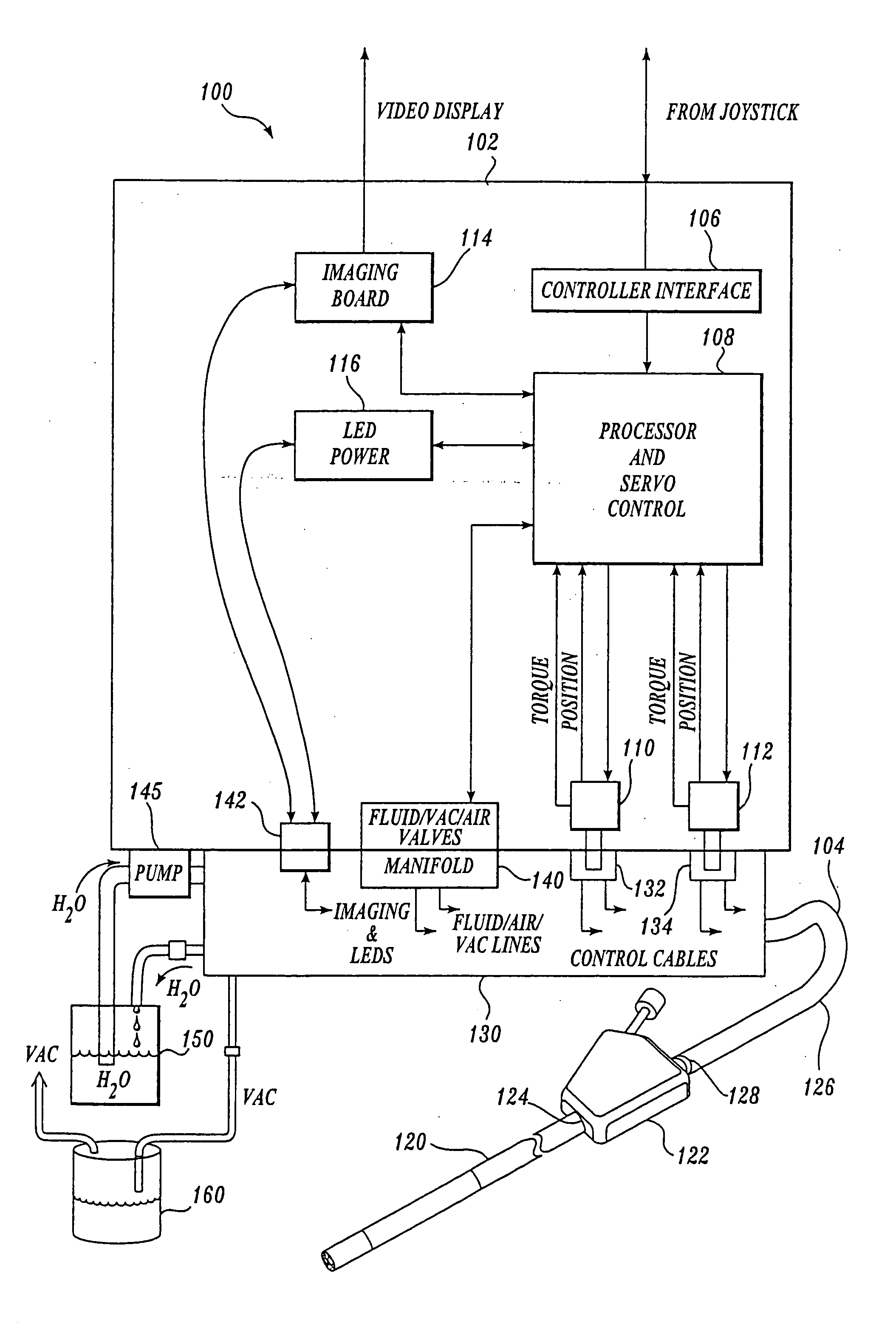
system. In one aspect, the system includes a control cabinet, a number of manual or electronic actuators that control the orientation of an endoscope and an imaging system to produce images collected by an
image sensor at the distal end of the endoscope. The endoscope is connectable with the control cabinet and used to examine and / or treat a patient. After the
examination procedure, the endoscope is disconnected from the control cabinet and may be disposed saving the cost and labor of cleaning and resterilization inherent in traditional reusable endoscopes.
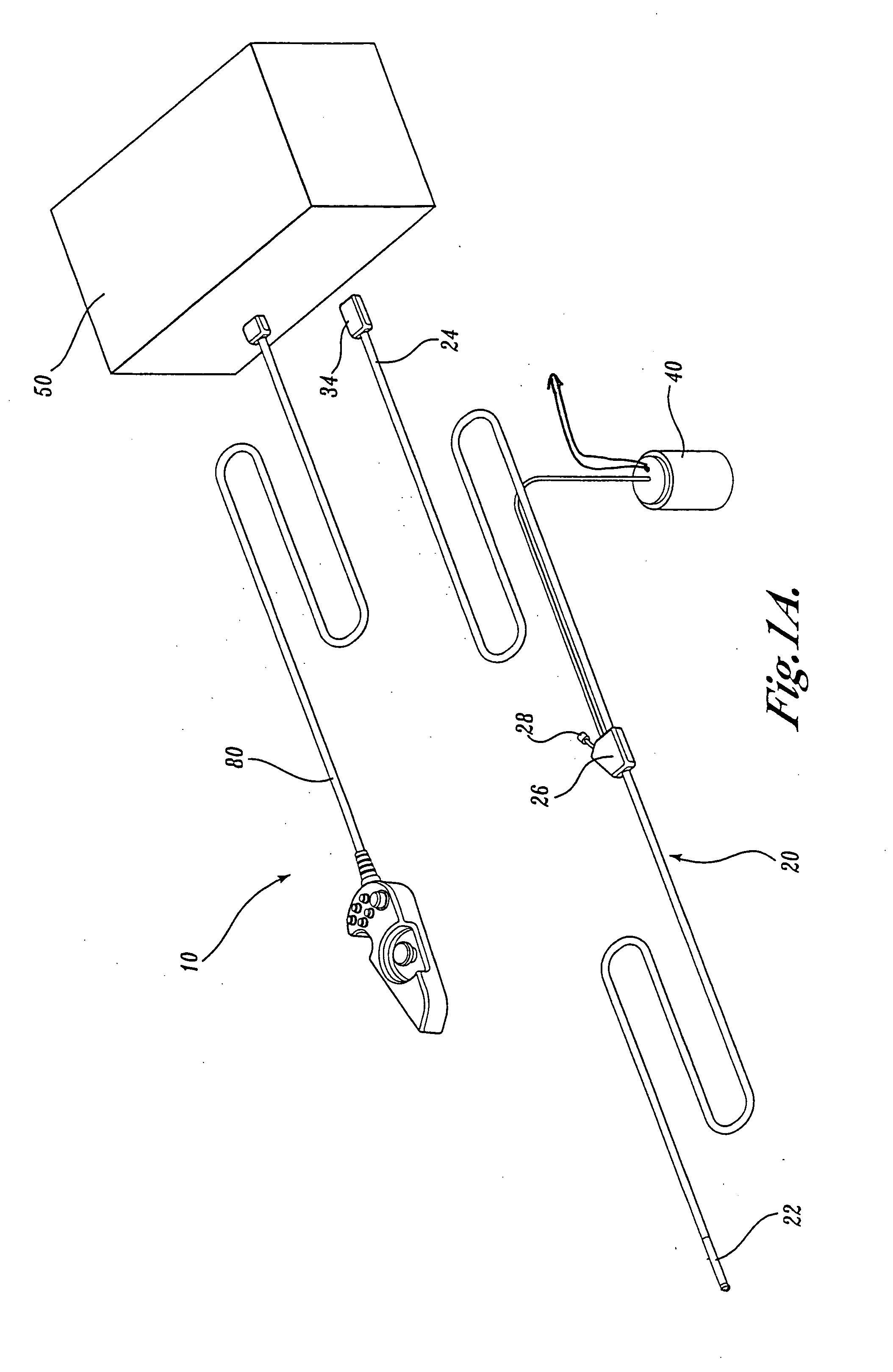
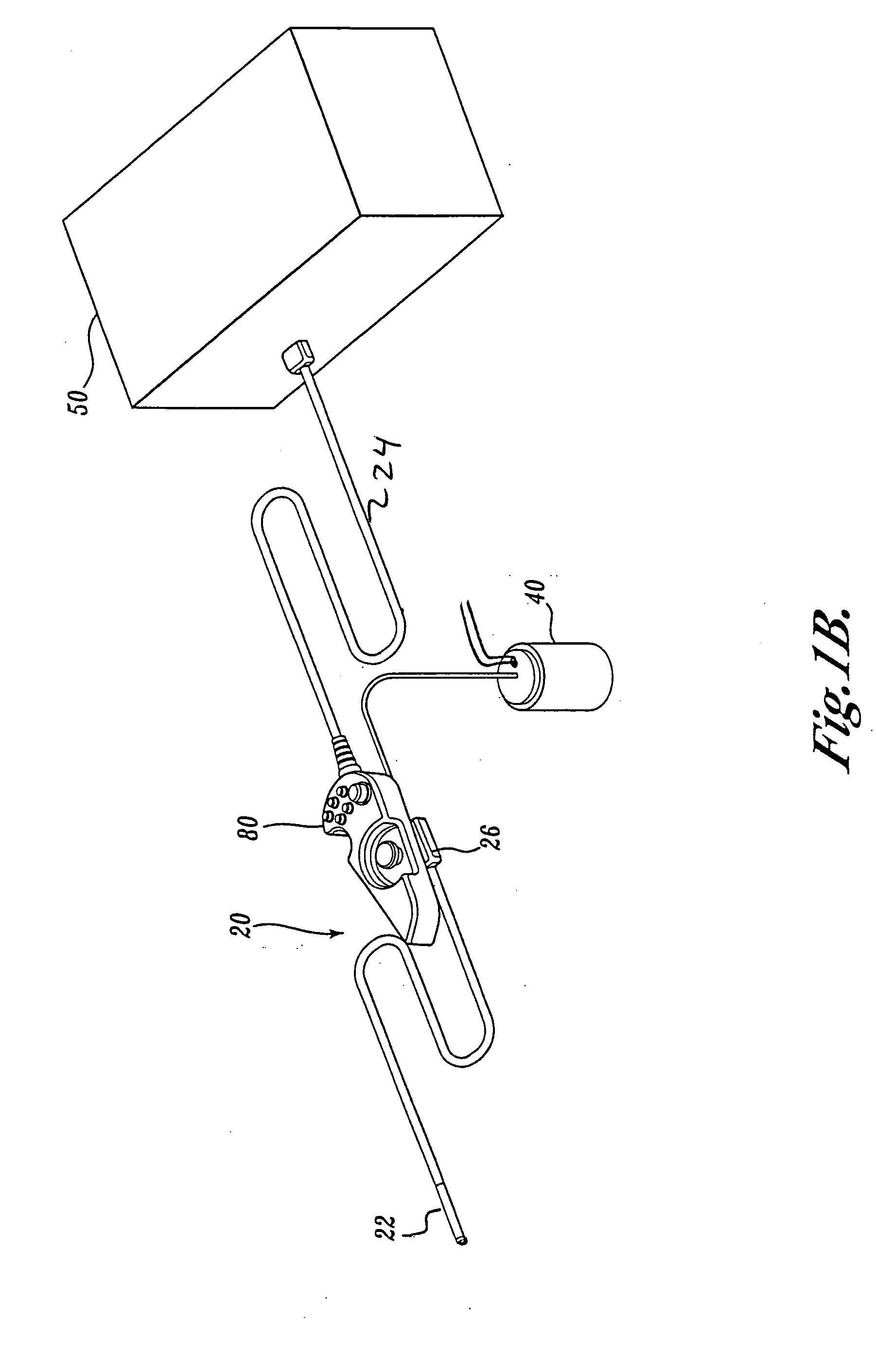
[0008] The endoscope of the present invention includes a flexible elongate tube or shaft and an illumination source that directs light onto an examination site. An
image sensor and objective lens
assembly at or adjacent the distal end of the endoscope captures reflected light to produce an image of the illuminated scene. Images produced by the sensor are transmitted to a
display device to be viewed by an operator. In one embodiment, an imaging
assembly at the distal end of the endoscope includes an inexpensive
mass-produceable assembly of components that house one or more light emitting diodes (LEDs), an image sensor such as a
CMOS solid state image sensor and low cost (e.g., plastic) lens assembly. The LEDs may be thermally coupled to a
heat exchanger, and air or liquid cooled in order to remove any
excess heat generated by the LEDs.
[0009] The endoscope of the present invention also includes a steering mechanism such as a number of tensile control cables, which allow the distal end of the endoscope to be deflected in a desired direction. In one embodiment of the invention, the proximal end of the tensile control cables is connected to a mechanical control mechanism (e.g., knobs)—mounted in a proximal control
handle. In another embodiment, the cables communicate with actuators within the control cabinet. In the latter, a directional controller generates
electrical control signals which are sent via a processor within the control cabinet, which generates control signals to drive the actuators in order to orient the distal end of the endoscope in the direction desired by the operator. In another embodiment of the invention, the distal end of the endoscope is automatically steered, based on analysis of images from the image sensor. A
joystick or other directional controller may include tactile, haptic or other sensory feedback to reflect the force against a tissue wall or to alert the operator that the endoscope may be looped. The distal tip housing provides a high degree of integration of parts—for example, clear windows for the LEDs are insert-molded into the distal tip housing to eliminate any secondary window sealing operations and to ensure a
hermetic seal.
[0010] In one embodiment of the invention, the endoscope includes an articulation joint that is comprised of a number of low cost (e.g.,
machine formed, stamped or molded parts), easily
mass produced components that allow the distal end of the endoscope to be bent in a desired direction by the control cables. In one embodiment of the invention, the articulation joint exerts a
restoring force such that upon release of a tensioning force, the distal end of the endoscope will straighten.
[0011] In another embodiment of the invention, the endoscope has a variation in stiffness along its length that allows the distal end to be relatively flexible while the more proximal regions of the endoscope have increased column strength and torque fidelity so that an operator can navigate the endoscope with greater ease and
accuracy and precision through tortuous, compliant
anatomy with fewer false advances (“loops”). A preset variation in mechanical properties (e.g., column strength, bending modulus or strength, torsion) along the length can be provided, for example, by varying the durometer rating or types or dimensions of materials that comprise a shaft of the endoscope. Operator-controlled
variable stiffness can be provided by control cables that can be tightened, loosened or torqued to adjust the stiffness of the shaft. In yet another embodiment, the spacing between the components that comprise the articulation joint is selected to provide a preset variation in stiffness along the length of the articulation joint.
[0013] In another embodiment of the invention, the endoscope surface includes a material such as a
hydrophilic coating, to reduce the
coefficient of friction of the endoscope. Other coatings may be used to, for example, improve the device performance, provide an indication of prior use or
contamination or deliver therapeutic agents.

