Projection Lens System of a Microlithographic Projection Exposure Installation

a technology of projection lens and exposure installation, which is applied in the direction of photomechanical treatment, printing, instruments, etc., can solve the problems of difficult to ensure a consistently high imaging quality during the projection operation, and similar problems moreover occur in the projection objective, so as to reduce the deployment of the manipulator

Inactive Publication Date: 2008-05-08
CARL ZEISS SMT GMBH
View PDF18 Cites 49 Cited by
  • Summary
  • Abstract
  • Description
  • Claims
  • Application Information

AI Technical Summary

Benefits of technology

[0014]It is an object of the invention to provide measures by which a high imaging quality can be ensured in HIIL immersion objectives, or in projection objectives in which liquid lenses are arranged. In particular, these measures are intended to make sure that variations of the imaging quality during the projection operation remain within tolerable limits.
[0018]c) an adjustable manipulator for reducing an image field curvature which is caused by heating of the medium during the projection operation.
[0025]However, the wavelength of the lasers conventionally used as light sources can be detuned only to a very limited extent. Furthermore, sizeable wavelength changes would also intolerably reduce the transmissivity of the optical elements of the projection objective. Merely by changing the wavelength, therefore, it is not possible to compensate for sizeable variations of the Petzval sum such as those typically caused by temperature changes in the medium.
[0028]As already mentioned, a temperature change of a medium with a positive refracting power generally causes a reduction of the Petzval sum. If only a reduction of the Petzval sum can likewise be achieved with the aid of the manipulator, then it is advantageous to deploy the manipulator in the basic state of the projection objective and reduce the deployment for the manipulator when the medium is heated.

Problems solved by technology

When using such HIIL immersion objectives, however, it has been found that it is difficult to ensure a consistently high imaging quality during the projection operation.
Similar problems moreover occur in projection objectives with liquid lenses which lie inside a projection objective.

Method used


Image

  • Projection Lens System of a Microlithographic Projection Exposure Installation
  • Projection Lens System of a Microlithographic Projection Exposure Installation
  • Projection Lens System of a Microlithographic Projection Exposure Installation

Examples


Embodiment Construction

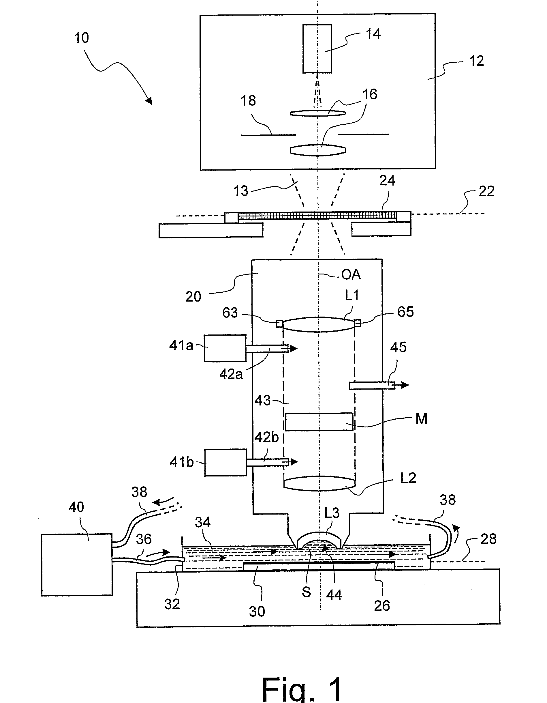
[0057]FIG. 1 shows a meridian section through a microlithographic projection exposure apparatus, denoted overall by 10, in a highly simplified schematic representation. The projection exposure apparatus 10 has an illumination device 12 for generating projection light 13, which contains inter alia a light source 14, illumination optics indicated by 16 and a field diaphragm 18. In the exemplary embodiment which is represented, the projection light has a wavelength of 193 nm. It is of course also possible to use other wavelengths, for example 157 nm or 248 nm.

[0058]The projection exposure apparatus 10 furthermore includes a projection objective 20 which contains a multiplicity of optical elements such as lenses, mirrors or filter elements. Three lenses L1, L2 and L3 are represented as examples of these in FIG. 1. The projection objective 20 is used to image a mask 24, which is arranged in an object plane 22 of the projection objective 20, onto a photosensitive layer 26 which, for examp...


PUM


Abstract

A microlithographic projection exposure apparatus comprises a projection objective which images an object onto an image plane and has a lens with a curved surface. In the projection objective there is a liquid or solid medium which directly adjoins the curved surface over a region which is usable for imaging the object. The projection exposure apparatus also has an adjustable manipulator for reducing an image field curvature which is caused by heating of the medium during the projection operation.

Description

CROSS-REFERENCE TO RELATED APPLICATIONS[0001]This is a national phase of international application PCT / EP2005 / 012327 filed Nov. 17, 2005, which claims priority under 35 U.S.C. §119(e)(1) to U.S. Provisional Application Ser. No. 60 / 629,126, filed Nov. 18, 2004. The entire content of this US application is incorporated herein by reference.BACKGROUND OF THE INVENTION[0002]1. Field of the Invention[0003]The present invention relates to projection objectives of microlithographic projection exposure apparatus, such as those used for the production of integrated circuits and other microstructured components.[0004]2. Description of the Prior Art[0005]For the production of large-scale integrated electrical circuits and other microstructured components, a plurality of structured layers is applied on a suitable substrate which, for example, may be a silicon wafer. In order to structure the layers, they are first covered with a photoresist which is sensitive to light of a particular wavelength ...

Claims


Application Information

Patent Timeline
Patent Type & Authority Applications(United States)
IPC IPC(8): G03B27/54G03B27/52
CPCG03F7/70891G03F7/70341
Inventor BEIERL, HELMUTBLEIDISTEL, SASCHASINGER, WOLFGANGGRUNER, TORALFEPPLE, ALEXANDERWABRA, NORBERTBEDER, SUSANNEWEBER, JOCHENFELDMANN, HEIKOSCHWAER, BAERBELROGALSKY, OLAFKAZI, ARI
Owner CARL ZEISS SMT GMBH
Why Eureka
Try Eureka