
Fluid applicator device and method of using same

a technology of fluid applicator and fluid reservoir, which is applied in the field of fluid applicator, can solve the problems of inability to easily regulate the pressure from one application to another, the volume of the container is not sufficient, and the thickness of the product is not suitable for application, so as to achieve easy and efficient manufacturing and marketing, and the effect of low production cost and low price of sal

Active Publication Date: 2008-05-08
BLISTEX INC
View PDF5 Cites 21 Cited by
  • Summary
  • Abstract
  • Description
  • Claims
  • Application Information

AI Technical Summary

Benefits of technology

[0011]To attain this, the present invention essentially comprises an applicator device having the interconnected elements of a container, a base, a shaft, a piston, a collar, a plurality of fluid conduction pathways, and an applicator head rotatably mounted within the collar in which a fluid held within the container may conveniently flow into the fluid conduction pathways and onto the applicator head so that the fluid may be gently rolled onto a user's epidermis, such as a user's lips.
[0021]Still yet another aspect of the present invention is to provide an applicator device that can dispense relatively high viscosity fluids onto a user's epidermis rather than thin, short-lasting liquids.

Problems solved by technology

Although these applicators have enjoyed wide use, they are unsuitable for use in applying thicker products.
Unfortunately, only thin or very low viscosity liquids can be easily applied with these types of applicators which sometimes requires the user to invert the applicator in order to dispense these thin liquid products.
However, these devices ordinarily require that the applicator means be mechanically or otherwise squeezed to deliver the product.
Devices of these types often suffer the disadvantage in that it is substantially difficult to deliver onto the epidermis sufficient quantities of relatively high viscosity fluids from the contents of the container.
This pressure cannot readily be regulated from one application to another.
While all of the above-described devices fulfill their respective, particular objectives and requirements, the aforementioned patents do not describe an applicator device having a container, a base, a shaft, a piston, a collar, a plurality of fluid conduction pathways, and an applicator head rotatably mounted within the collar and so that a viscous fluid held within the container may easily flow into the fluid conduction pathways and onto the applicator head to soothingly present the viscous fluid onto a user's lips.

Method used


Image

  • Fluid applicator device and method of using same
  • Fluid applicator device and method of using same
  • Fluid applicator device and method of using same

Examples


Embodiment Construction

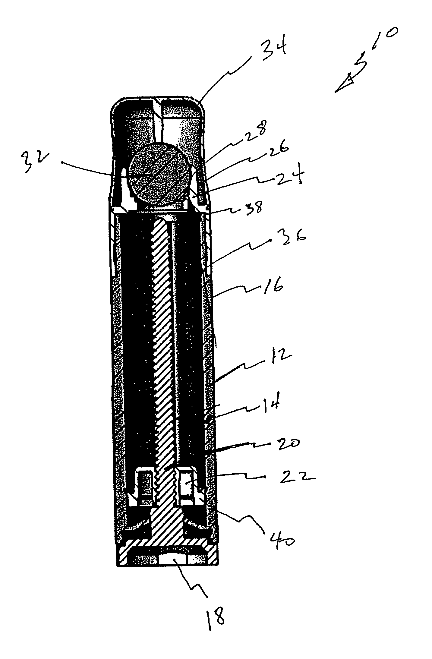
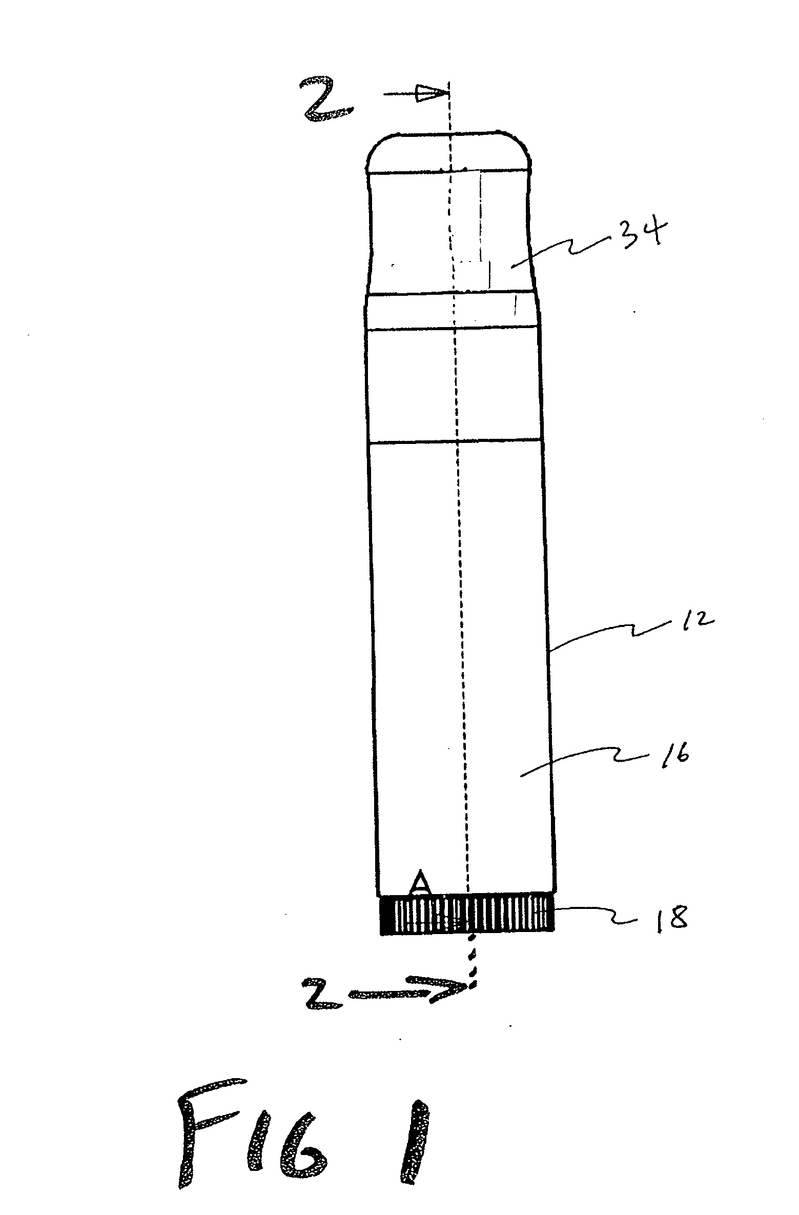
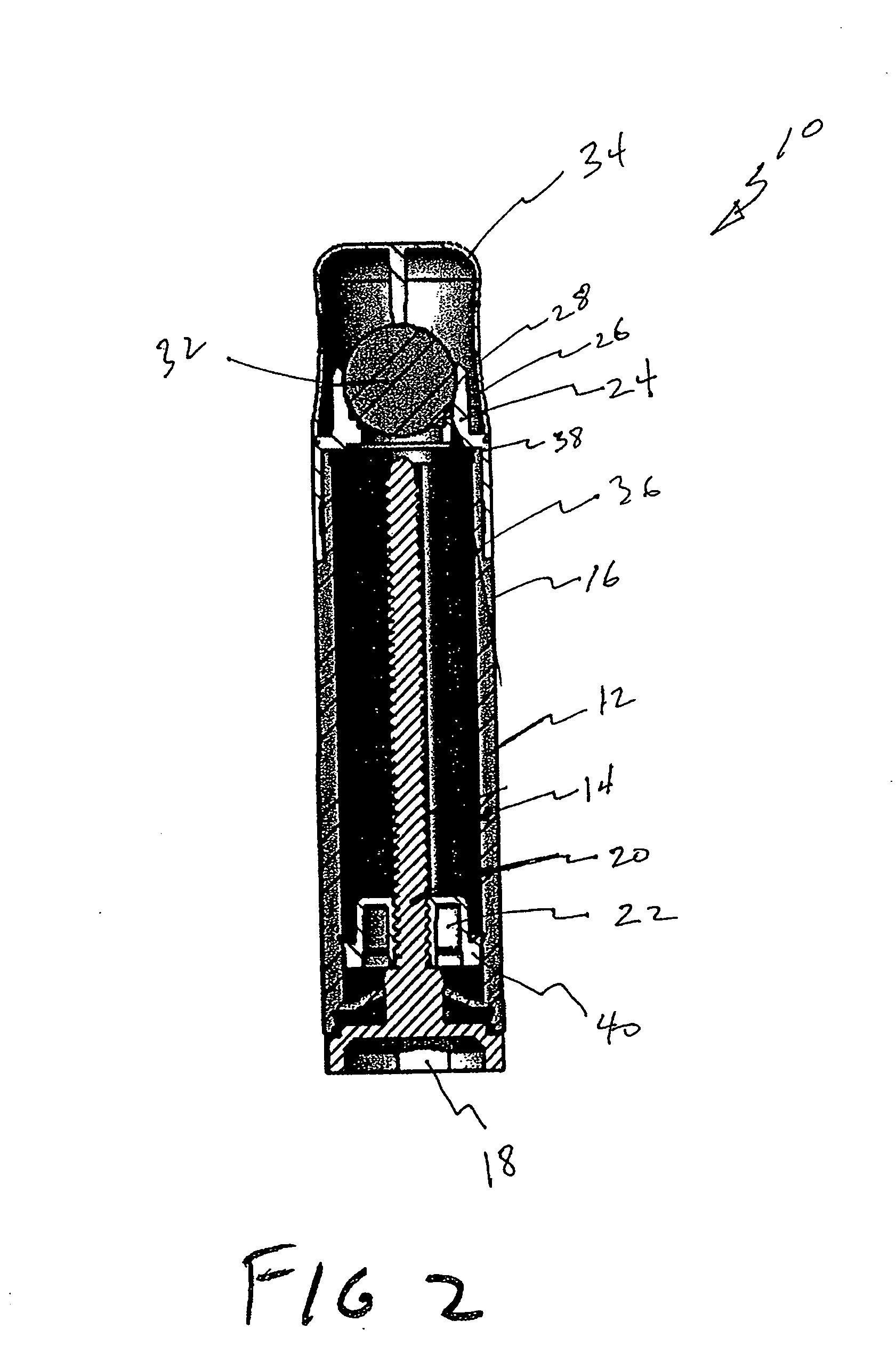
[0033]Referring now to the drawings, and in particular FIGS. 1 to 5 thereof, one preferred embodiment of the present invention is shown and generally designated by the reference numeral 10. One preferred embodiment of the applicator device 10 comprises a container 12, a base 18, a shaft 20, a piston 22, a plurality of fluid conduction pathways 30, and an applicator head 32. The container 12 has an interior and exterior surface (14 and 16, respectively). The base 18 is attached to the container 12. The shaft 20 is attached to the base 18. The piston 22 is attached to the shaft 20 in which the piston 22 is configured to be slidably fitted against the interior surface 14 of the container 12. The collar 24 is attached to the container 12 in which the collar 24 has an inner surface 26 and an outer surface 28. The plurality of fluid conduction pathways 30 are cut into the inner surface 26 of the collar 24. The applicator head 32 is rotatably mounted within the collar 24 in which the appli...


PUM


Abstract

A fluid applicator device having the interconnected components of a container, a base, a shaft, a piston, a collar, a plurality of fluid conduction pathways and an applicator head is presented. The applicator head is rotatably mounted within the collar and slidably held in place by the inner surface of the collar. The inner surface of the collar also has a plurality of fluid conduction pathways cut into it so that a viscous fluid confined within the container may be flow into the fluid conduction pathways and onto the applicator head so that it may be soothingly applied onto a portion of a user's epidermis such as onto the lips of a user. The method of using the applicator device includes the acts of manipulating, obtaining, pressing, removing, returning, rolling, and withdrawing.

Description

FIELD OF THE INVENTION[0001]The present invention relates to a fluid applicator. More particularly, it concerns fluid applicator devices and associated methods of using the devices that are especially adapted to apply fluids onto the epidermis of humans. The present invention has particular utility in applying viscous fluids such as cosmetic creams, lipstick substrates, lotions, lip care moisturizing products, and pharmaceutical products onto lips.DESCRIPTION OF THE PRIOR ART[0002]A large variety of liquid applicators have been disclosed in the prior art. Perhaps one of the most widely used applicators is of the so-called ball roll-on type applicator. These are exemplified in U.S. Pat. Nos. 2,749,566; 2,923,957 and 2,998,616 and rely on the fact that the ball rotating in the liquid contained in a bottle picks up the liquid as it dips into the contents of the container and applies it to the body area on which the ball is rolled.[0003]Although these applicators have enjoyed wide use, ...

Claims


Application Information

Patent Timeline
Patent Type & Authority Applications(United States)
IPC IPC(8): B43K7/10B43K23/08B43M11/02
CPCA45D40/261A61M35/003A45D2200/055
Inventor WOJCIK, MICHAELSANBORN, KELLY
Owner BLISTEX INC
Learn More