Centrifugal force-based microfluidic device for nucleic acid extraction and microfluidic system including the microfluidic device

a microfluidic device and centrifugal force technology, applied in the direction of machines/engines, biomass after-treatment, specific gravity measurement, etc., can solve the problems of difficult control of fluid flow and temperature of elementary units in the body of revolution

Active Publication Date: 2008-05-08
PRECISIONBIOSENSOR INC
View PDF3 Cites 96 Cited by
  • Summary
  • Abstract
  • Description
  • Claims
  • Application Information

AI Technical Summary

Benefits of technology

[0023] According to another aspect of the present invention, there is provided a microfluidic system including: a microfluidic device comprising a body of revolution, a microfluidic structure disposed in the body of revolution, each comprising a plurality of chambers, channels connecting the chambers and valves disposed in the channels to control fluid flow, the microfluidic structure transmitting the fluid using centrifugal force due to rotation of the body of revolution, and micro-particles contained in any one of the chambers which selectively collect target materials from biomaterial samples flowing into the chamber; a rotation operating unit which rotates the body of revolution of the microfluidic device; and an external energy source which irradiates electromagnetic waves onto the micro-partic...

Problems solved by technology

However, in this case, since a body of revolution is not fixed onto a frame and thus moves, i...

Method used


Image

  • Centrifugal force-based microfluidic device for nucleic acid extraction and microfluidic system including the microfluidic device
  • Centrifugal force-based microfluidic device for nucleic acid extraction and microfluidic system including the microfluidic device
  • Centrifugal force-based microfluidic device for nucleic acid extraction and microfluidic system including the microfluidic device

Examples


Embodiment Construction

[0050] Hereinafter, the present invention will be described more fully with reference to the accompanying drawings, in which exemplary embodiments of the invention are shown.

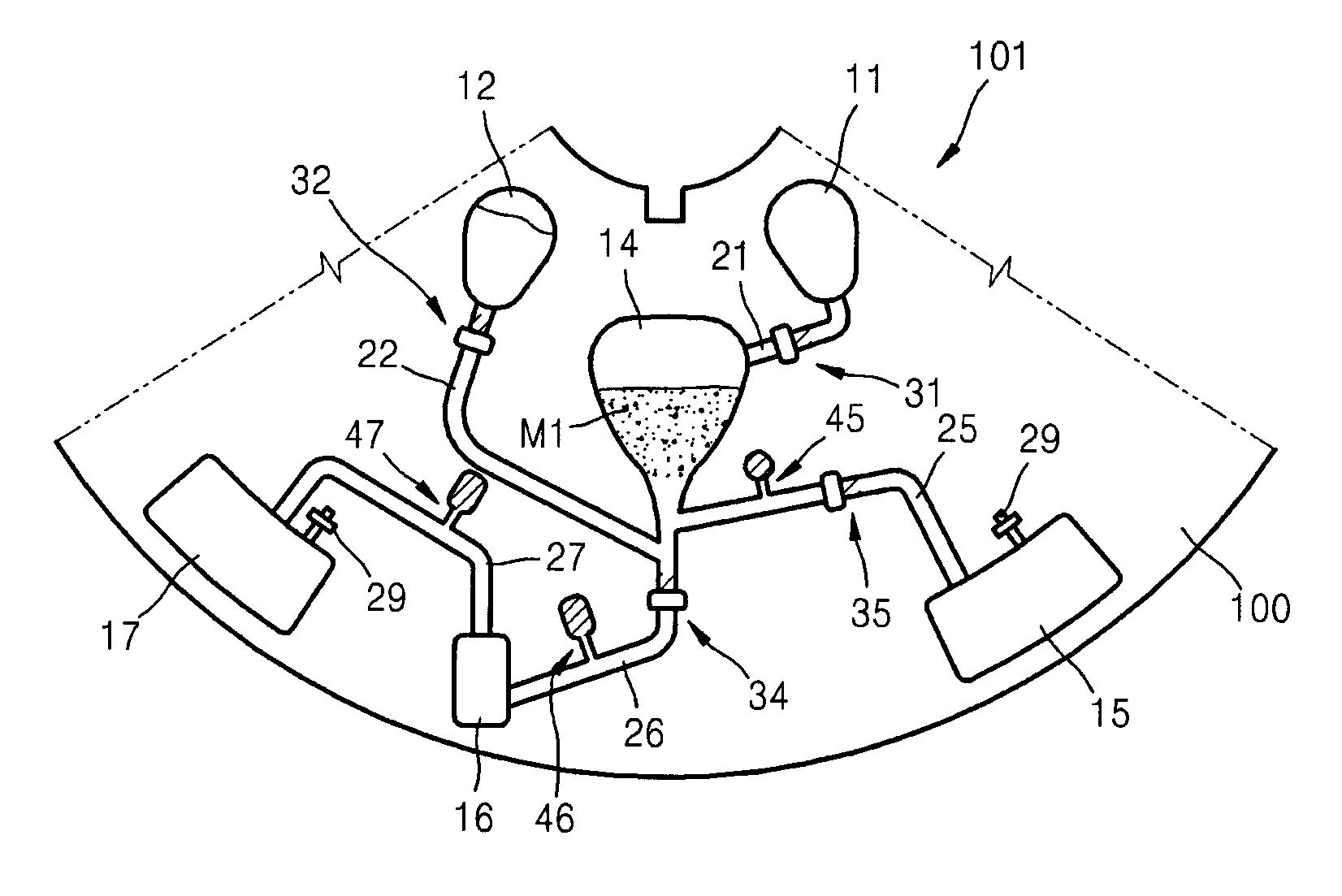
[0051]FIG. 1 is a plan view schematically illustrating a microfluidic device 101 for nucleic acid extraction according to an exemplary embodiment of the present invention.

[0052] Referring to FIG. 1, the microfluidic device 101 according to the current exemplary embodiment of the present invention has a symmetric shape and includes a disk-shaped body of revolution 100. The body of revolution 100 may include one or more microfluidic structures. For example, the body of revolution 100 may be divided into a plurality of fan-shaped regions and a microfluidic structure can be prepared on each region. FIG. 1 illustrates one section of the body of revolution 100 on which a microfluidic structure is prepared. The upper part and lower part of the section of the body of revolution 100 of FIG. 1 is a center part and an ou...


PUM

PropertyMeasurementUnit
Densityaaaaaaaaaa
Speedaaaaaaaaaa
Distanceaaaaaaaaaa

Abstract

A centrifugal force-based microfluidic device for nucleic acid extraction and a microfluidic system are provided. The microfluidic device includes a body of revolution; a microfluidic structure disposed in the body of revolution, the microfluidic structure including a plurality of chambers, channels connecting the chambers, and valves disposed in the channels to control fluid flow, the microfluidic structure transmitting the fluid using centrifugal force due to rotation of the body of revolution; and magnetic beads contained in one of the chambers which collect a target material from a biomaterial sample flowing into the chamber, wherein the microfluidic structure washes the magnetic beads which collect the target material, and separates nucleic acid by electromagnetic wave irradiation from an external energy source to the magnetic beads. The microfluidic system includes the microfluidic device; a rotation operating unit which rotates the body of revolution; and an external energy source which irradiates electromagnetic waves.

Description

CROSS-REFERENCE TO RELATED PATENT APPLICATIONS [0001] This application claims priority from Korean Patent Application No. 10-2006-0085371, filed on Sep. 5, 2006, and Korean Patent Application No. 10-2006-0125084, filed on 8 Dec., 2006, in the Korean Intellectual Property Office, the disclosures of which are incorporated herein in their entirety by reference. BACKGROUND OF THE INVENTION [0002] 1. Field of the Invention [0003] Apparatuses and methods consistent with the present invention relate to a centrifugal force-based microfluidic device which controls fluid flow by centrifugal force in a microfluidic structure prepared on a body of revolution, and more particularly, to a centrifugal force-based microfluidic device for extracting nucleic acid of a target cell or a virus from a biological sample. [0004] 2. Description of the Related Art [0005] In general, a microfluidic structure constituting a microfluidic device may include a plurality of elementary units, such as a chamber, a c...

Claims


Application Information

Patent Timeline
IPC IPC(8): C12N13/00B04B5/10C12M1/10
CPCB01F13/0059F16K2099/0084B01F15/0233B01L3/502738B01L3/502753B01L3/502761B01L2300/0806B01L2300/0867B01L2300/087B01L2400/0409B01L2400/0677F16K99/0001F16K99/0017F16K99/0019F16K99/0032F16K99/004F16K2099/0076B01F15/0201B01F33/30B01F35/71725B01F35/71
Inventor CHO, YOON-KYOUNGLEE, JEONG-GUNLEE, BEOM-SEOKPARK, JONG-MYEON
Owner PRECISIONBIOSENSOR INC
Why Eureka
Try Eureka