Manipulator

a manipulator and mandrel technology, applied in the field of manipulators, can solve the problems of large angular range, difficult to mount bellows or flexible covers on joints, and difficult to make them of electrically insulating materials or cover or coat them with electric insulators

Inactive Publication Date: 2008-05-08
TERUMO KK +1
View PDF4 Cites 975 Cited by
  • Summary
  • Abstract
  • Description
  • Claims
  • Application Information

AI Technical Summary

Benefits of technology

[0010]It is one of the objects of the present invention to provide a manipulator which prevents power transmitting memb

Problems solved by technology

Since the wires and gears disposed in the joints serve as power transmitting members, it is difficult to make them of an electrically insulating material or cover or coat them with an electric insulator.
However, it is difficult to mount bellows or flexible covers on the joints which make bending motions in a relatively large angular range.
Even if bellows or fl

Method used


Image

  • Manipulator
  • Manipulator
  • Manipulator

Examples


first embodiment

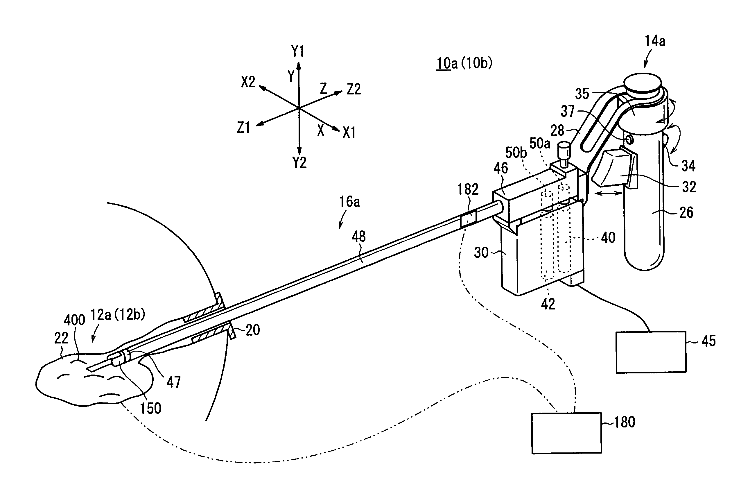
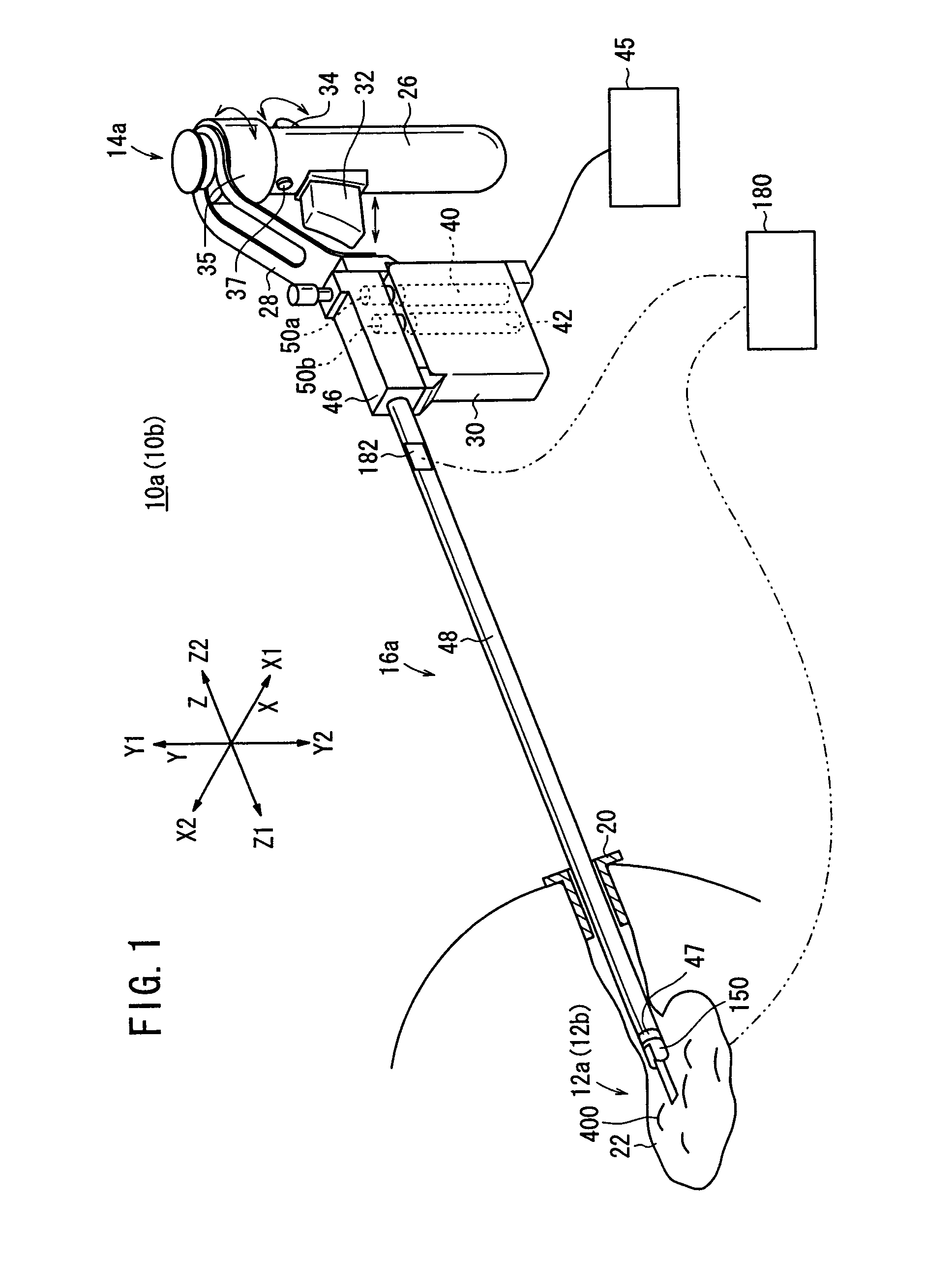
[0086]A manipulator 10b according to a modification of the manipulator 10a will be described below with reference to FIGS. 12 through 16.

[0087]The manipulator 10b is similar to the manipulator 10a in that it has the same operation command unit 14a and the same connector 16a, but is different from the manipulator 10a in that it has a working unit 12b instead of the working unit 12a. The working unit 12b comprises a wire-driven mechanism 200, a drive mechanism 202, and an end effector (acting unit) 204.

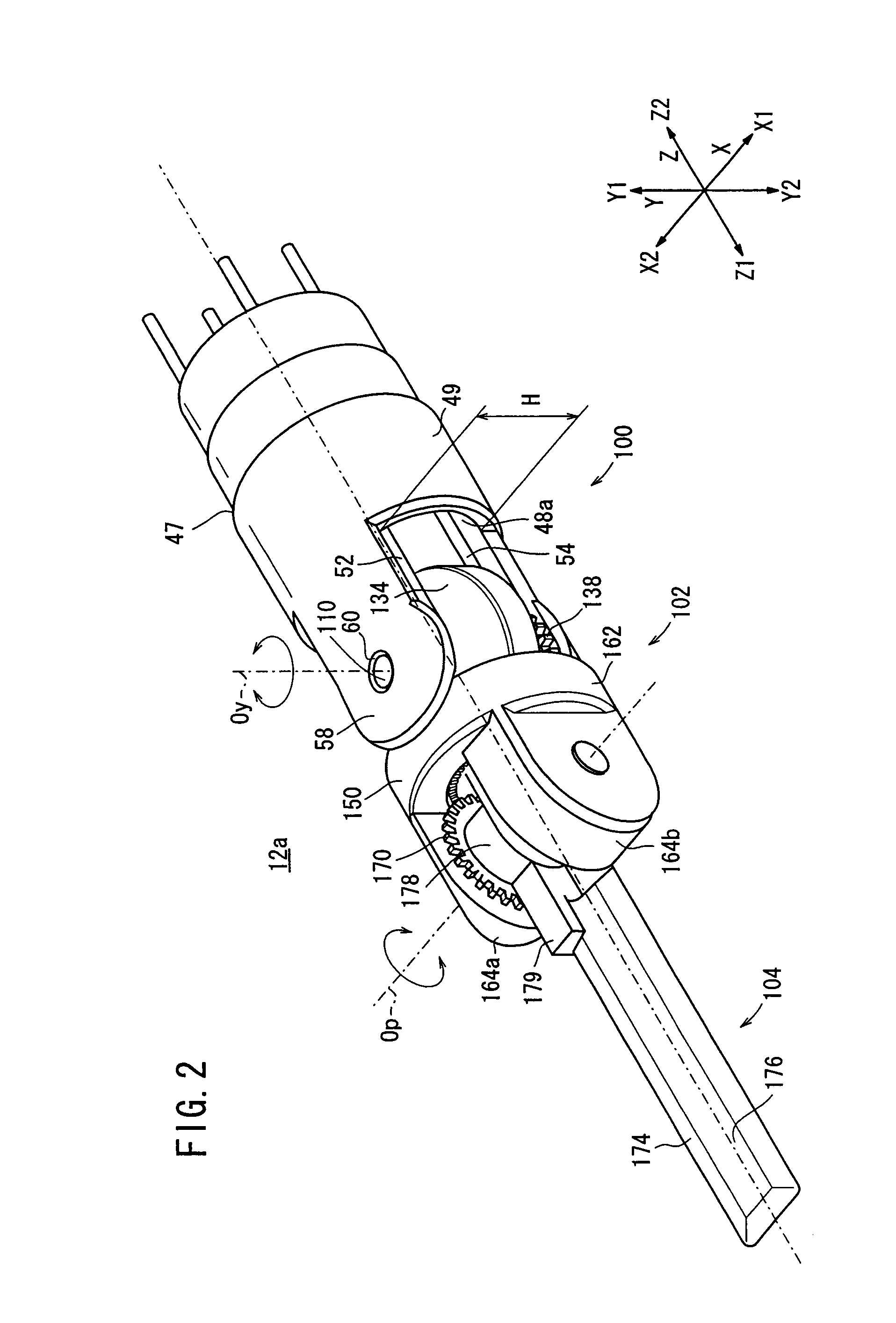
[0088]As shown in FIG. 12, the working unit 12b incorporates therein a mechanism of two degrees of freedom. The mechanism includes a first degree of freedom for angularly moving a portion of the working unit 12b that is positioned ahead of the first rotational axis Oy extending along the Y direction, in yawing directions about the first rotational axis Oy, and a second degree of freedom for angularly moving the portion of the working unit 12b in rolling directions about the second rota...

second embodiment

[0104]A manipulator 10c according to the present invention will be described below with reference to FIGS. 17 through 21.

[0105]The manipulator 10c is different from the manipulator 10a in that it has a connector 16b and an operation command unit (operating unit) 14b instead of the connector 16a and the operation command unit 14a, and it has a working unit 12c instead of the working unit 12a.

[0106]The operation command unit 14b includes, in the actuator block 30, a motor 44 in addition to the motors 40, 42, disposed parallel to the motors 40, 42, for operating respective mechanisms having three degrees of freedom provided in the working unit 12c.

[0107]The proximal joint 46 of the connector 16b houses therein a drive pulley (third rotational source) 50c connected to the drive shaft of the motor 44. A wire (third flexible power transmitting member) 56 is trained around the drive pulley 50c and extends through the hollow region 48a in the connector shaft 48 to the working unit 12c, as...


PUM


Abstract

A manipulator includes a working unit comprising an operation command unit, horizontal roller and vertical rollers mounted thereon, drive pulleys rotatable in response to operation of the horizontal roller and the vertical roller, a connector, a first rotational axis disposed on a distal end of the connector, a second rotational axis extending perpendicularly to the first rotational axis, tubular members rotatably supported on a shaft providing the first rotational axis, and wires having rear and front portions trained around the drive pulleys and the tubular members, respectively. A drive mechanism operates about the first rotational axis in response to rotation of the tubular member, and an end effector operates about the second rotational axis in response to rotation of the tubular member.

Description

BACKGROUND OF THE INVENTION[0001]1. Field of the Invention[0002]The present invention relates to a manipulator for actuating a working unit through power transmitting members by operating an operating unit.[0003]2. Description of the Related Art[0004]Heretofore, there has been used in the art a medical manipulator having an end working unit and a hand operating unit which are connected to each other by a connector. Under endoscopic observation, the hand operating unit is held by hand and operated to insert the end working unit into a body cavity and then actuate the end working unit to perform various medical treatments on the living tissue.[0005]Japanese Laid-Open Patent Publication No. 2003-61969 and Japanese Laid-Open Patent Publication No. 2002-102248 disclose a manipulator having a working unit which incorporates a pair of grippers for gripping a living tissue. The grippers can be opened and closed about a gripper shaft, and can be angularly movable in unison about a pitch axis...

Claims


Application Information

Patent Timeline
IPC IPC(8): F16D3/60
CPCA61B19/22A61B2017/00929A61B2019/4027A61B2017/2939A61B2019/2242A61B2017/2927A61B2090/0427A61B34/70A61B34/71
Inventor JINNO, MAKOTOSUNAOSHI, TAKAMITSUUENOHARA, SHUICHI
Owner TERUMO KK
Why Eureka
Try Eureka