Apparatus and method for stabilizing an image from an endoscopic camera

an endoscopic camera and image stabilization technology, applied in the field of apparatus and method for stabilizing an image from an endoscopic camera, can solve problems such as difficulty in interpreting information displayed on the screen, and achieve the effect of preventing the rotation of the image sensor

Inactive Publication Date: 2008-05-08
WIITA BRUCE E +1
View PDF13 Cites 102 Cited by
  • Summary
  • Abstract
  • Description
  • Claims
  • Application Information

AI Technical Summary

Problems solved by technology

Such rotation of the displayed image can make it difficult to interpret the information displayed on the screen.

Method used


Image

  • Apparatus and method for stabilizing an image from an endoscopic camera
  • Apparatus and method for stabilizing an image from an endoscopic camera
  • Apparatus and method for stabilizing an image from an endoscopic camera

Examples


first embodiment

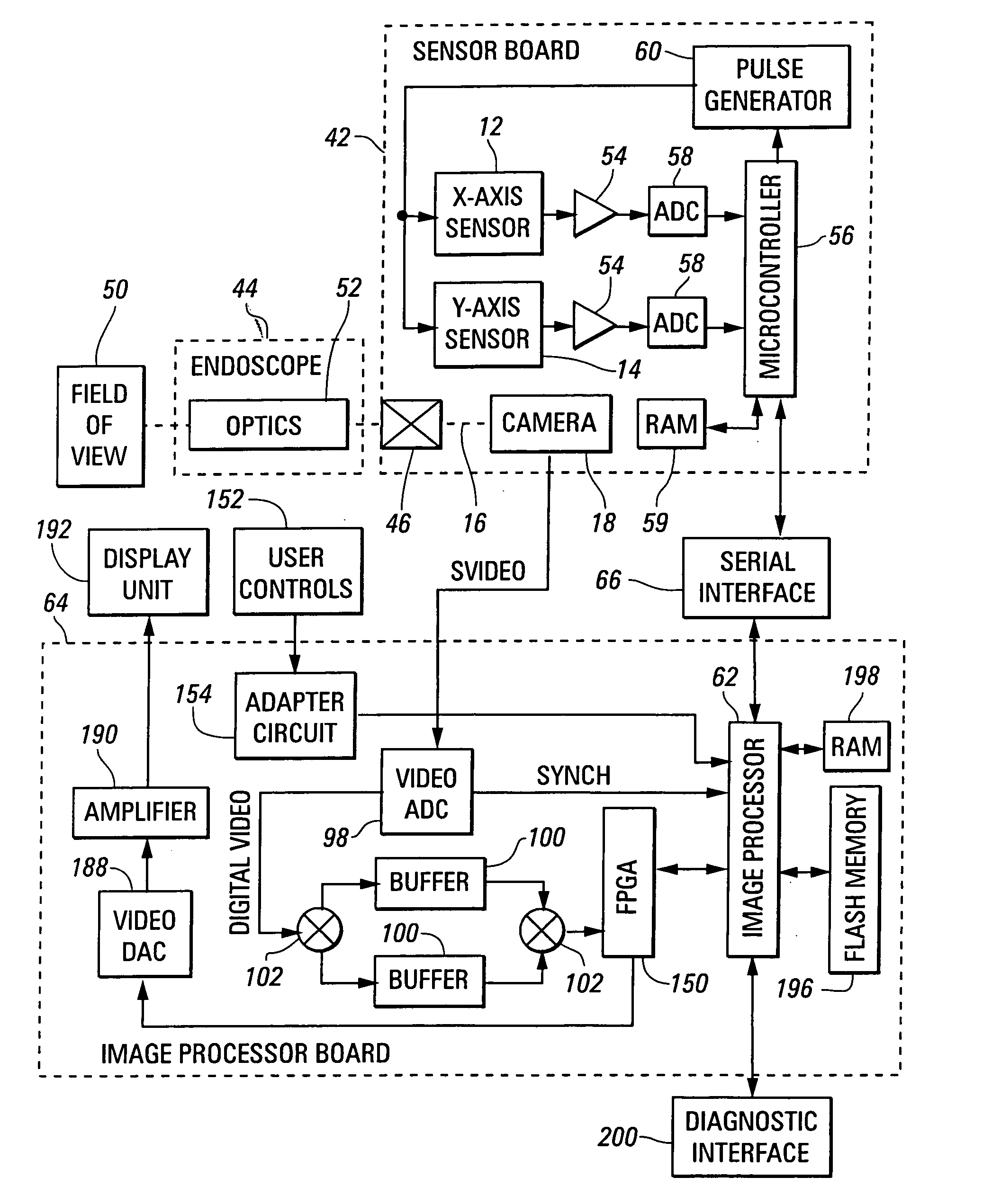
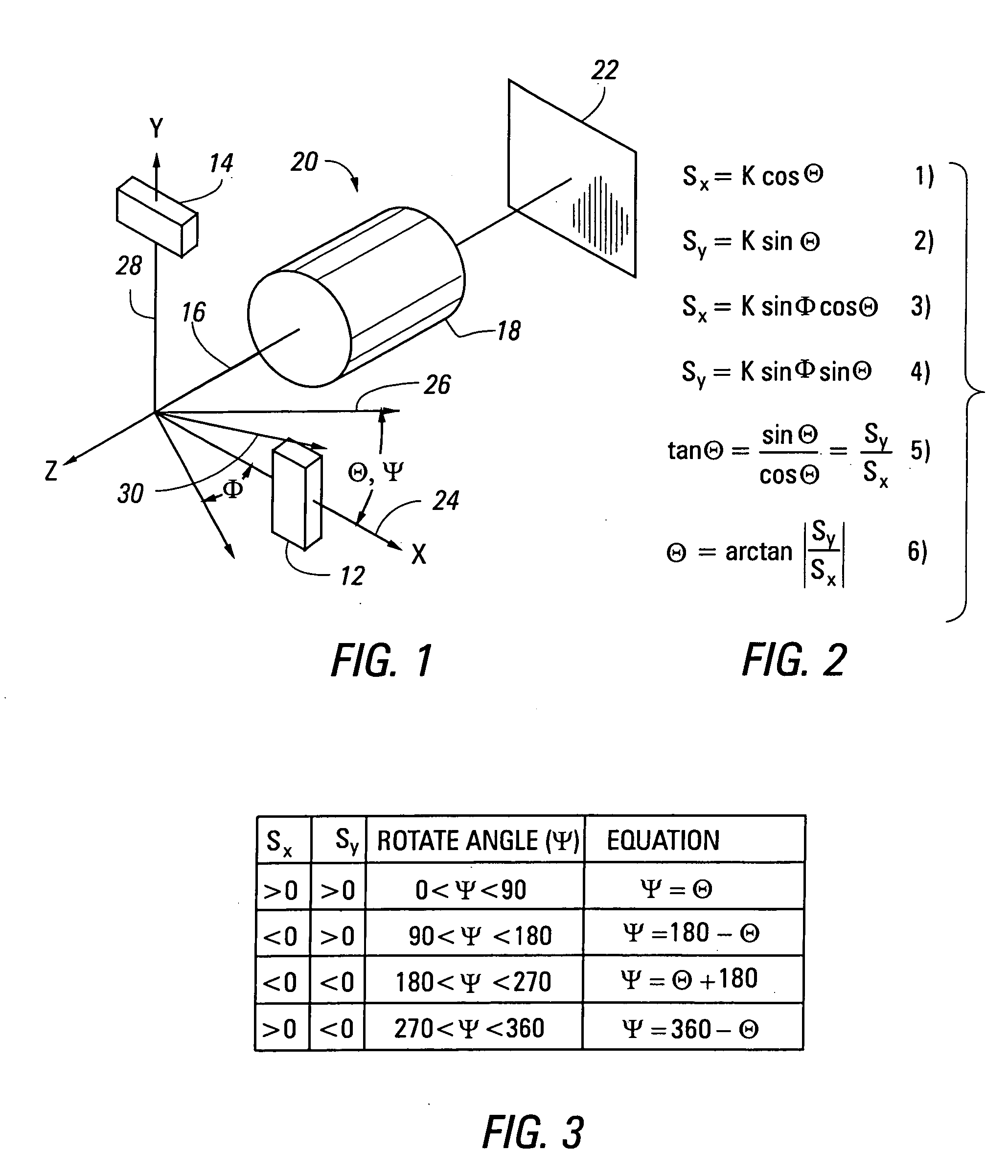
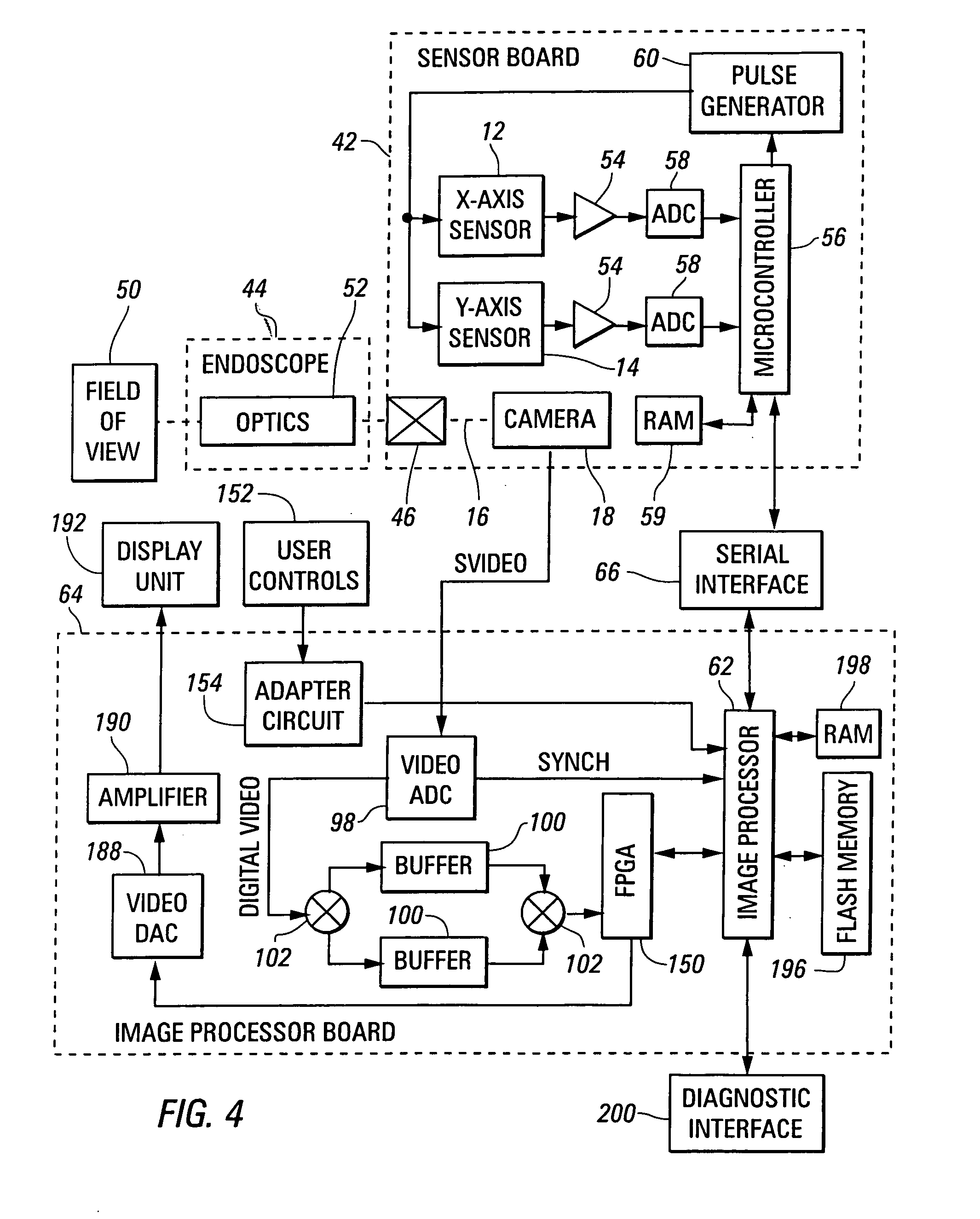
[0034]FIG. 1 is a schematic view of apparatus 10 for sensing rotational orientation built in accordance with the invention to include an X-axis sensor 12 and a Y-axis sensor 14, oriented perpendicularly to one another in an x-y plane perpendicular to an axis of image rotation 16 of optics 18 within a video camera unit 20, which is focused on an image sensor 22 to form a video image within an endoscope. The axis of image rotation 16 is defined as an axis about which rotation of the camera unit 20 causes rotation of an image formed from an output signal produced in the image sensor 22. The camera unit 12 may be mounted to rotate within the endoscope about the axis of image rotation 16, or the camera unit 12 and the endoscope together may be rotated, deliberately or inadvertently within the body cavity to cause rotation of the camera unit about the axis of image rotation 16. If the camera unit 20 is mounted to rotate within the endoscope, the axis of such rotation is preferably aligned...

second embodiment

[0057]FIG. 9 is a schematic view of apparatus 210 built in accordance with the invention to include a first pair of direction sensors 12, 14, mounted as described above in reference to FIG. 1 to determine the angular relationship of the camera unit 18 relative to a first ambient field acting in a direction indicated by arrow 30, and additionally to include a second pair of direction sensors 212, 214. Like the direction sensors 12, the direction sensors 212, 214 are mounted so that the directions in which they sense an ambient field are perpendicular to one another, and so that these directions of field sensing are additionally perpendicular to the axis of image rotation 16 of the camera unit 18. The additional direction sensors 212, 214 sense another type of ambient field, extending in a different direction, as indicated by arrow 216.

[0058]Optionally, an first z-axis sensor 217, sensing a component of the first ambient field in the Z-direction 218, and a second z-axis sensor 220, se...


PUM


Abstract

A video camera unit used with an endoscope is provided with sensors sensing an ambient field to detect rotation of the camera unit about an axis causing rotation of an image generated from the output signal of the camera unit. This output signal is modified to produce a stabilized video signal, producing an image held at a preferred angle. In one embodiment, two ambient fields, such as gravity and a magnetic field are alternately used.

Description

BACKGROUND OF THE INVENTION[0001]1. Field of the Invention[0002]This invention relates to stabilization of an image produced from the output signal of a video camera used with an endoscope, and, more particularly, to eliminating the rotation of the displayed image caused by rotation of the video camera.[0003]2. Summary of the Background Art[0004]A video camera is often used with, or as a part of, an endoscope in diagnostic or surgical procedures, with images generated from the video camera signals being displayed on the screen of a display monitor for use by the surgeon and other individuals during the procedures. However, as the endoscope is maneuvered through various channels within the patient's body, and as the endoscope and the video camera are further maneuvered to place a particular tissue structure within the field of view of the video camera, the camera is often rotated about its optical axis, causing the image displayed on the monitor screen to be similarly rotated. Such r...

Claims


Application Information

Patent Timeline
Patent Type & Authority Applications(United States)
IPC IPC(8): A61B1/05
CPCA61B1/05
Inventor WIITA, BRUCE E.WITTA, GREGORY D.
Owner WIITA BRUCE E
Why Eureka
Try Eureka