Method for enhanced data analysis with specialized video enabled software tools for medical environments
What is AI technical title?
AI technical title is built by Patsnap AI team. It summarizes the technical point description of the patent document.
a software tool and enhanced data technology, applied in the field of medical software tools, can solve the problems of poor visibility, surgeons must deal with, and the number of challenges, and achieve the effect of facilitating equipment integration
Active Publication Date: 2019-05-09
WADE JACK
View PDF12 Cites 11 Cited by
Summary
Abstract
Description
Claims
Application Information
AI Technical Summary
This helps you quickly interpret patents by identifying the three key elements:
Problems solved by technology
Method used
Benefits of technology
Benefits of technology
[0007]Various embodiments of the disclosed technology provide a medical software tools platform that utilizes a surgical display to provide access to medical software tools, such as medically-oriented applications or widgets, that can assist those in the operating room, such as a surgeon and their surgical team, with a surgery. For various embodiments, the medical. software tools platform and its associated medical software tools are presented on a surgical display (e.g., being utilized in an operating room) over an image stream provided by a surgical camera (e.g., in use in the operating room) or other medical device that generates image streams. An image stream can include video or a series of static images (e.g., medical ultrasound device). Various medical software tools can provide features and functions that can facilitate integration of equipment in an operating room or add medical context awareness to anatomic structures presented in the image stream from the surgical camera.
[0008]Medical video display panels and multiscreen displays are commonly employed in such contexts as hospital operating theaters or any facility where surgical operations are carried out in a sterile environment. They are used to display visual information from data streams such as surgical imagery from an endoscope, patient vital signs, patient medical records, clinical imaging data (patient CT scans, MRIs, etc.), outputs from other operating room equipment, and operating room environmental status. Surgical displays and multi-screen video displays provide a surgeon and their surgical team with visual information that can be automatically updated, or can be used to enable collaboration among viewers. Where a surgical display or multiscreen video display is used for group collaboration, there is generally a requirement that the group has the ability to update and reconfigure the visual information displayed, which is usually facilitated through a video switch. Traditional video switches are controlled through a switch box, a keyboard, or a local connection (via an RS-232 port or Ethernet port) and have only a single point for control access. In some contexts, visual data streams to a single large panel video display or a multiscreen display configuration are provided by two or more computer systems, each being controlled by a computer operator (i.e., user) using such input / output (IO) devices as keyboards, mice, and as video monitor. At times, it is convenient for the computer operator to share the IO devices between the computers by means of a device that switches the IO devices between the multiple computers. These switches, often referred to as a Keyboard-Video-Mouse (KVM) switch, are commanded by the computer operator (e.g., commanded by a special keyboard sequence or a button on the KVM switch) to switch a common keyboard, mouse, or video monitor between controlling the computer systems.
[0009]According to some embodiments, a system comprises an image stream interface module configured to receive an image stream from a surgical camera, a user interface overlay module configured to provide a user interface overlay adapted for presentation over the image stream, and a medical software tools module configured to provide a medical software tool through the user interface overlay. The medical software tool may be configured to perform an operation with respect to the image stream and provide an output adapted to be presented over the image stream. The user interface overlay can include a graphical user interface (GUI) that permits visibility of at least some of the image stream underlying the user interface overlay. The user interface overlay module is further configured to present the output over the image stream. Depending on the embodiment, the surgical camera may be an endoscope or a laparoscope. Additionally, the image stream interface module may receive the image stream from the surgical camera through an image stream processing system.
Problems solved by technology
While this brings many benefits to patients, it presents a number of challenges for the surgeon who must work within a very confined surgical compartment.
In particular, surgeons must deal with poor visibility, limited lighting, and a narrow viewing angle.
Because of their size, conventional medical imaging devices tend to have limited imaging resolution, often fail to provide more than one perspective of biological tissue, and due to visible lighting constraints, often fail to show differences in biological tissue.
Method used
Image
Click on the blue label to locate the original text in one second.
Reading with bidirectional positioning of images and text.
Examples
Embodiment Construction
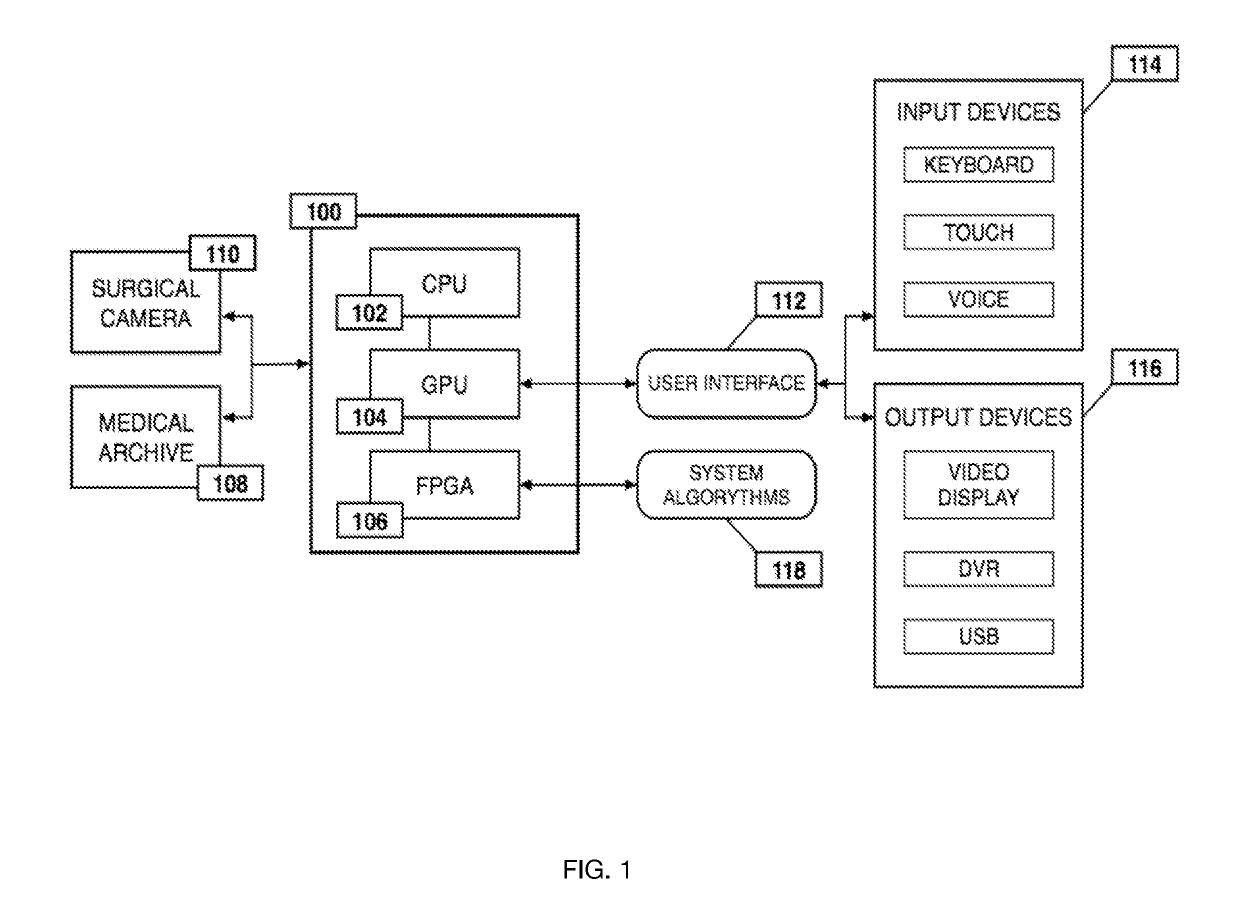
[0052]FIG. 1 is a block diagram illustrating an example of the overall processing system that may be used in implementing various features of embodiments of the disclosed technology. In accordance with the preferred embodiment of the present invention, the processing system 100 consists of processor elements such as: a central processing unit (CPU) 102; a graphics processing unit (GPU) 104; and a field programmable gate array (FPGA) 106. The processing system 100 may be used to retrieve and process raw data derived from a surgical camera 110 or a data storage device, such as a medical archive 108. The surgical camera 110 or medical archive 108 transmits a data stream to the processing system 100, whereby that data is processed by the CPU 102. The FPGA 106, connected to the CPU 102 and the GPU 104, simultaneously processes the received data by using a series of programmed system algorithms 118, thus functioning as an image clarifier within the processing system 100. The GPU 104 commu...
PUM
Abstract
Medical software tools platforms utilize a surgical display to provide access to specific medical software tools, such as medically-oriented applications or widgets, that can assist surgeons or surgical team in performing various procedures. In particular, an endoscopic camera may register the momentary rise in the optical signature reflected from a tissue surface and in turn transmit it to a medical image processing system which can also receive patient heart rate data and display relevant anomalies. Changes in various spectral components and the speed at which they change in relation to a source of stimulus (heartbeat, breathing, light source modulation, etc.) may indicate the arrival of blood, contrast agents or oxygen absorption. Combinations of these may indicate various states of differing disease or margins of tumors, and so forth. Also, changes in temperatures, physical dimensions, pressures, photoacoustic pressures and the rate of change may indicate tissue anomalies in comparison to historic values.
Description
PRIORITY CLAIMS[0001]This application claims the benefit and is a continuation of U.S. patent application Ser. No. 15 / 958,983, filed Apr. 20, 2018, which is a continuation of U.S. patent application Ser. No. 15 / 789,948, filed Oct. 20, 2017, which is a continuation in part, claims the benefit of U.S. patent application Ser. No. 15 / 652,031, filed Jul. 17, 2017, which is a continuation in part of U.S. patent application Ser. No. 15 / 456,458, filed Mar. 10, 2017, which is a continuation in part of U.S. patent application Ser. No. 15 / 377,817, filed Dec. 13, 2016, which is a continuation of U.S. patent application Ser. No. 14 / 107,329, filed Dec. 16, 2013, and issued as U.S. Pat. No. 9,526,586 on Dec. 27, 2016, which claims the benefit of U.S. Provisional Patent Application Ser. No. 61 / 865,037, filed Aug. 12, 2013. This application also claims the benefit of and is a continuation in part of U.S. patent application Ser. No. 15 / 170,575, filed Jun. 1, 2016, which claims the benefit of 13 / 430,4...
Claims
Application Information
Patent Timeline
Application Date:The date an application was filed.
Publication Date:The date a patent or application was officially published.
First Publication Date:The earliest publication date of a patent with the same application number.
Issue Date:Publication date of the patent grant document.
PCT Entry Date:The Entry date of PCT National Phase.
Estimated Expiry Date:The statutory expiry date of a patent right according to the Patent Law, and it is the longest term of protection that the patent right can achieve without the termination of the patent right due to other reasons(Term extension factor has been taken into account ).
Invalid Date:Actual expiry date is based on effective date or publication date of legal transaction data of invalid patent.
Patent Type & AuthorityApplications(United States)

