Flow Controllers

a flow controller and fluid technology, applied in the direction of multiple way valves, valve arrangements, other medical devices, etc., can solve the problems of contaminating the blood collected for transfusion, requiring a minimum amount of skill and training, and residing bacteria on the donor's skin where the needle is placed

Inactive Publication Date: 2008-05-08
FENWAL
View PDF99 Cites 103 Cited by
  • Summary
  • Abstract
  • Description
  • Claims
  • Application Information

AI Technical Summary

Benefits of technology

[0014]Accordingly, in one aspect, a flow controller is provided with a body defining a cavity. The body includes a fluid inlet, a first fluid outlet, and a second fluid outlet. An actuator member is at least partially received within the cavity and defines a first flow channel and a second flow channel. The actuator member is adapted for at least substantially non-rotational movement from a first position to a second position within the cavity. In the first position, the first flow channel allows for fluid communication between the fluid inlet and the first fluid outlet. In the second position, the second flow channel allows for fluid communication between the fluid inlet and the second fluid outlet. The actuator member is prevented from moving from the second position to the first position.
[0015]In another aspect, a flow controller is provided with a body defining a cavity. The body includes a fluid inlet, a first fluid outlet, and a second fluid outlet. A generally cup-shaped insert is received within the cavity and has an inlet hole aligned with the fluid inlet, a first outlet hole aligned with the first fluid outlet, and a second outlet hole aligned with the second fluid outlet. An actuator member is at least partially received within the insert for movement from a first posit

Problems solved by technology

Collecting the sample prior to the main collection reduces the risk that bacteria residing on the donor's skin where the needle is inserted (i.e., in particular, the small section of detached skin commonly referred to as the “skin plug”) will enter the collection container and contaminate the blood collected for transfusion.
One possible drawback of such devices is that a minimum amount of skill and training may be required for a user to recognize the various positions and properly manipulate the dev

Method used


Image

  • Flow Controllers
  • Flow Controllers
  • Flow Controllers

Examples


Embodiment Construction

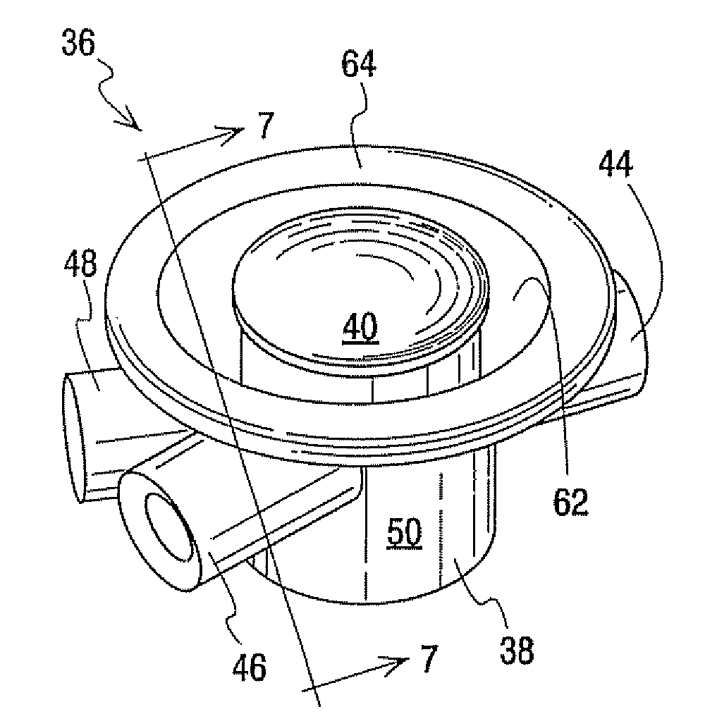
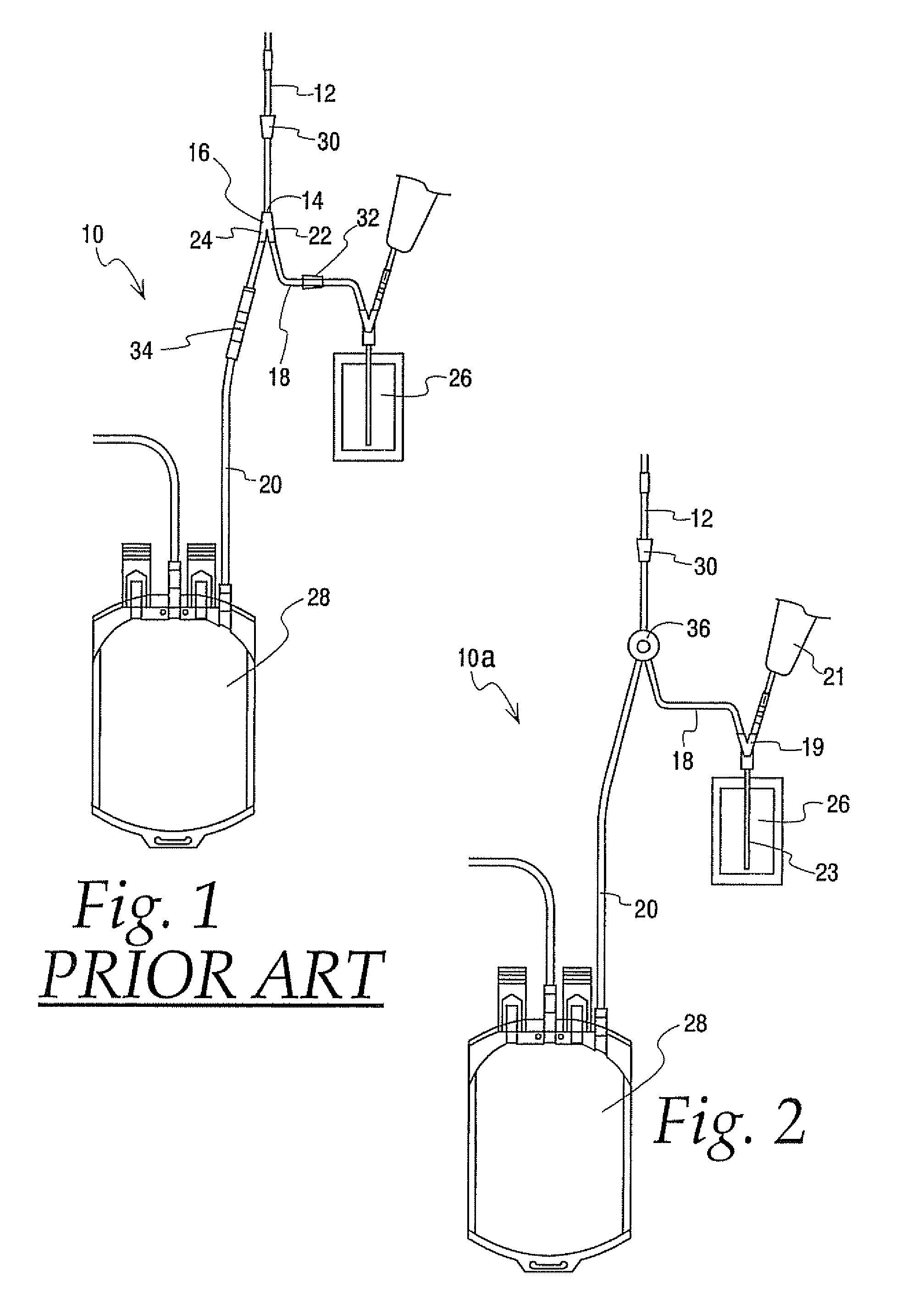
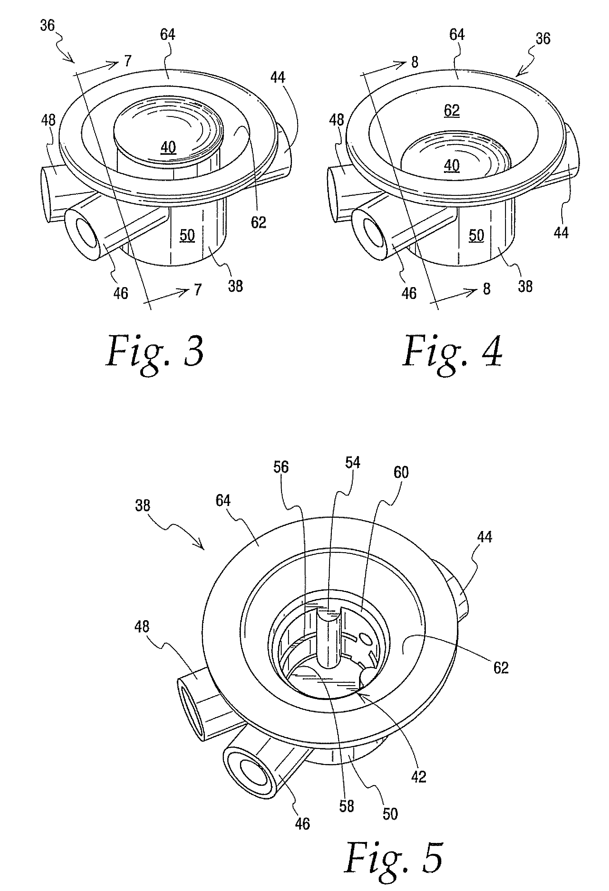
[0051]It will be seen from the following description that there are several possible variations and embodiments of flow controllers according to the present invention, including the flow controllers generally shown in FIGS. 1-23 and the flow controllers shown in FIGS. 24-27. Common to all of the embodiments described and shown below is a flow controller having a body (e.g., element 38 of FIG. 3 and element 146 of FIG. 24) with a fluid inlet (e.g., element 44 of FIG. 3 and element 150 of FIG. 24) and first and second fluid outlets (e.g., elements 46 and 48, respectively, of FIG. 3 and elements 152 and 154, respectively, of FIG. 24). The body is adapted to receive an actuator member (e.g., element 40 of FIG. 3 and element 156 of FIG. 24). As will be described in further detail below, the actuator member is further adapted for movement within the body to selectively bring the fluid inlet into communication with the first fluid inlet or second fluid outlet. The actuator is adapted for a...


PUM


Abstract

Flow controllers are provided for interconnecting a fluid source to two separate collection zones. The flow controllers include a body having a fluid inlet communicating with the source and two fluid outlets, each communicating with one of the collection zones. An actuator member received within a cavity of the body includes first and second flow paths. In a first position, the first flow path is aligned with the fluid inlet of the body to allow fluid communication with one of the fluid outlets and the associated collection zone. The actuator member is non-rotationally moved to a second position within the cavity to align the second flow path with the fluid inlet of the body, thereby halting flow through the first flow path and allowing fluid communication with the other collection zone. An optional safety feature prevents movement of the actuator member from the second position to the first position.

Description

BACKGROUND[0001]1. Field of the Disclosure[0002]This disclosure generally relates to apparatus for controlling fluid, such as in (but not limited to) the collection of blood from a donor, in particular blood collected in at least two separate containers. More particularly, the disclosure relates to valves suitable for switching blood flow between first and second blood collection containers. Even more particularly, this disclosure relates to directing initial blood flow from a donor to a first container and irreversibly diverting the blood flow to a second container.[0003]2. Description of Related Art[0004]A disposable plastic container and tubing set or fluid circuit is typically used for collecting blood from a donor. The disposable blood collection set includes a venipuncture needle for insertion into the arm of the donor. The needle is attached to one end of a flexible plastic tube which provides a flow path for the blood. The flow path communicates with one or more plastic bags...

Claims


Application Information

Patent Timeline
IPC IPC(8): A61M39/22
CPCA61M1/0209A61M5/16804A61M1/0236F16K11/0853F16K11/0856A61M39/223
Inventor MATHIAS, JEAN-MARIEWEST, RICHARD L.RONDEAU, GEORGESBOWMAN, JOSEPH H.GRANT, BENJAMIN S.BISCHOF, DANIEL F.
Owner FENWAL
Why Eureka
Try Eureka