
Annular support structures

a technology of annula and support rod, which is applied in the field of reinforcing lumen rings, can solve the problems of lumen diameter reduction and stenosis, and achieve the effect of suppressing or preventing the incidence of stenosis

Inactive Publication Date: 2008-05-15
TYCO HEALTHCARE GRP LP
View PDF99 Cites 234 Cited by
  • Summary
  • Abstract
  • Description
  • Claims
  • Application Information

AI Technical Summary

Benefits of technology

The patent text describes a support structure for a circular stapling instrument that helps maintain the anastomotic lumen (the space where the staples are formed) in an open condition. The support structure includes a rigid or semi-rigid annular ring that is attached to the staple cartridge assembly. The annular ring can be connected to the assembly using adhesive or friction engagement. The support structure can also include a wound closure material, such as adhesive, hemostat, or sealant, to help close the wound after use of the instrument. The annular ring can be made of stainless steel or titanium, and can have interstitial spaces to allow the staples to pass through. The support structure helps ensure the stapling instrument is effective and easy to use.

Problems solved by technology

One possible side effect of any end-to-end bowel anastomosis is its tendency to stenos over time, which stenosis can decrease the diameter of the lumen over time.

Method used


Image

  • Annular support structures
  • Annular support structures
  • Annular support structures

Examples


Embodiment Construction

[0051]Preferred embodiments of the presently disclosed support structure will now be described in detail with reference to the drawing figures wherein like reference numerals identify similar or identical elements.

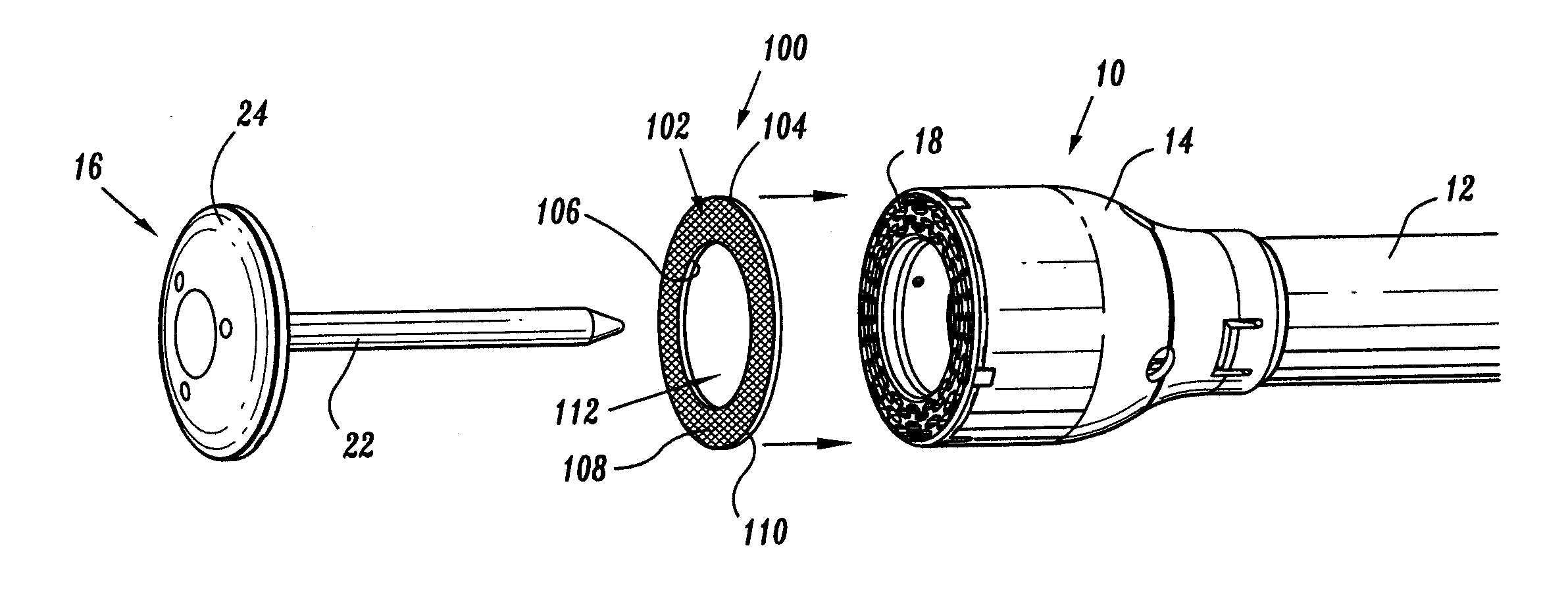
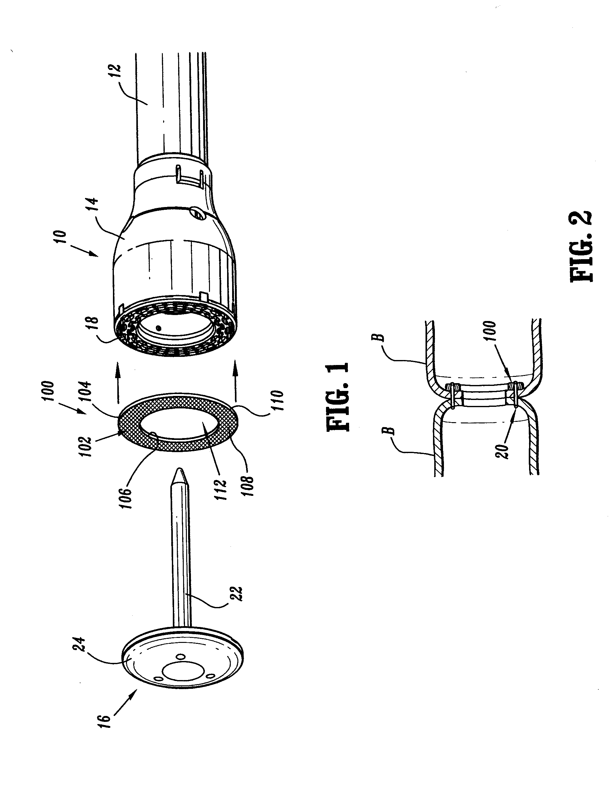
[0052]Referring initially in detail to FIG. 1, a surgical stapling support structure in the form of a lumen reinforcing ring, in accordance with an embodiment of the present disclosure, is generally shown as 100. Reinforcing ring 100 includes an annular ring 102 defined by an outer terminal edge 104, an inner terminal edge 106, an upper surface 108 and a lower surface 110. Inner terminal edge 106 of reinforcing ring 100 defines a central opening 112.

[0053]As seen in FIG. 1, reinforcing ring 100 cooperates with a circular stapling apparatus 10. Stapling apparatus 10 includes an elongated neck 12 having a staple cartridge assembly 14 operatively coupled to an end thereof and an anvil assembly 16 configured and adapted to removably engage the distal end of staple cartridge as...


PUM

PropertyMeasurementUnit
diameteraaaaaaaaaa
outer diameteraaaaaaaaaa
adhesiveaaaaaaaaaa

Abstract

Reinforcing lumen rings are configured and adapted for use in conjunction with a circular endoscopic stapling instrument having a staple cartridge assembly and an anvil assembly. The reinforcing lumen rings maintain anastomotic lumen, e.g. as formed by the circular endoscopic stapling apparatus, in an open condition. The reinforcing lumen rings can include an annular ring having an outer terminal edge and an inner terminal edge, the outer terminal edge having a diameter which is substantially equal to an outer diameter of the staple cartridge assembly and the inner terminal edge having a diameter which is substantially equal to an inner diameter of the staple cartridge assembly.

Description

CROSS-REFERENCE TO RELATED APPLICATIONS[0001]The present application claims the benefit of and priority to U.S. Provisional Patent Application Ser. No. 60 / 389,567 filed on Jun. 17, 2002, the entire contents of which are incorporated herein by reference.BACKGROUND[0002]1. Technical Field[0003]The present disclosure relates to annular support structures and, more particularly, to reinforcing lumen rings, for use in conjunction with a circular endoscopic stapling instrument, for maintaining the resulting anastomotic lumen in an open condition.[0004]2. Background of Related Art[0005]Staples have traditionally been used to replace suturing when joining or anastomosing various body structures, such as, for example, the bowel or bronchus. The surgical stapling devices employed to apply these staples are generally designed to simultaneously cut and seal an extended segment of tissue in a patient, thus, vastly reducing the time and risks of such procedures.[0006]Linear surgical stapling devi...

Claims


Application Information

Patent Timeline
Patent Type & Authority Applications(United States)
IPC IPC(8): A61B17/115A61B17/00A61B17/072A61B17/08A61B17/11
CPCA61B17/00491A61B17/07292A61B17/1114A61B17/068A61B17/1155A61B2017/07214A61B2017/1132A61B17/115
Inventor ORBAN, JOSEPH P.NOLAN, TIMOTHY
Owner TYCO HEALTHCARE GRP LP
Learn More