Rigid mouse pad

a mouse pad and rigid technology, applied in the field of flocked objects, can solve the problems of insufficient rigidity of the mouse pad, inability to accurately and/or precisely control the movement of the mouse, and inability to operate when positioned on an uneven surface such as a user's lap, etc., and achieve the effect of superior mouse pad surface performan

Inactive Publication Date: 2008-05-15
HIGH VOLTAGE GRAPHICS
View PDF99 Cites 33 Cited by
  • Summary
  • Abstract
  • Description
  • Claims
  • Application Information

AI Technical Summary

Benefits of technology

[0007]In one embodiment, the present invention generally relates to a flocked rigid mouse pad and a method of manufacturing them with flock appliques. The rigid mouse pads can exhibit superior mouse pad surface performance, not only when positioned on flat, horizontal surfaces but particularly when positioned on uneven, unleveled, undulated, and / or non-horizontal surfaces. Rigid mouse pads do not conform to undulated surfaces as conventional pliable mouse pads do. The rigid mouse pad surface can engage the mouse consistently along the entire mouse stroke and allow for the mouse stroke length desired by users, not only when positioned on a conventional flat, horizontal surface but also when positioned on an undulated surface, such as, a user's lap or the arm of an armchair.

Problems solved by technology

For example, surfaces that do not properly “engage” the mouse position tracking device typically do not accurately and / or precisely control cursor movement or provide for efficient or accurate command entry.
Additional problems may be encountered when a user seeks to operate the mouse without a rigid work surface.
While the mouse pads of the prior art provide for frictional engagement between the mouse pad and work surface by the non-slip backing, the mouse pad is not sufficiently rigid to be operated when positioned on an uneven surface such as a user's lap.
Unfortunately, these are typically locations where the resilient mouse pads of the prior art cannot be positioned on a flat, horizontal rigid surface.
The mouse cannot properly contact the undulated mouse pad 101 of FIG. 7A, and the resulting mousing action will be erratic or not work at all.

Method used


Image

  • Rigid mouse pad
  • Rigid mouse pad
  • Rigid mouse pad

Examples


Embodiment Construction

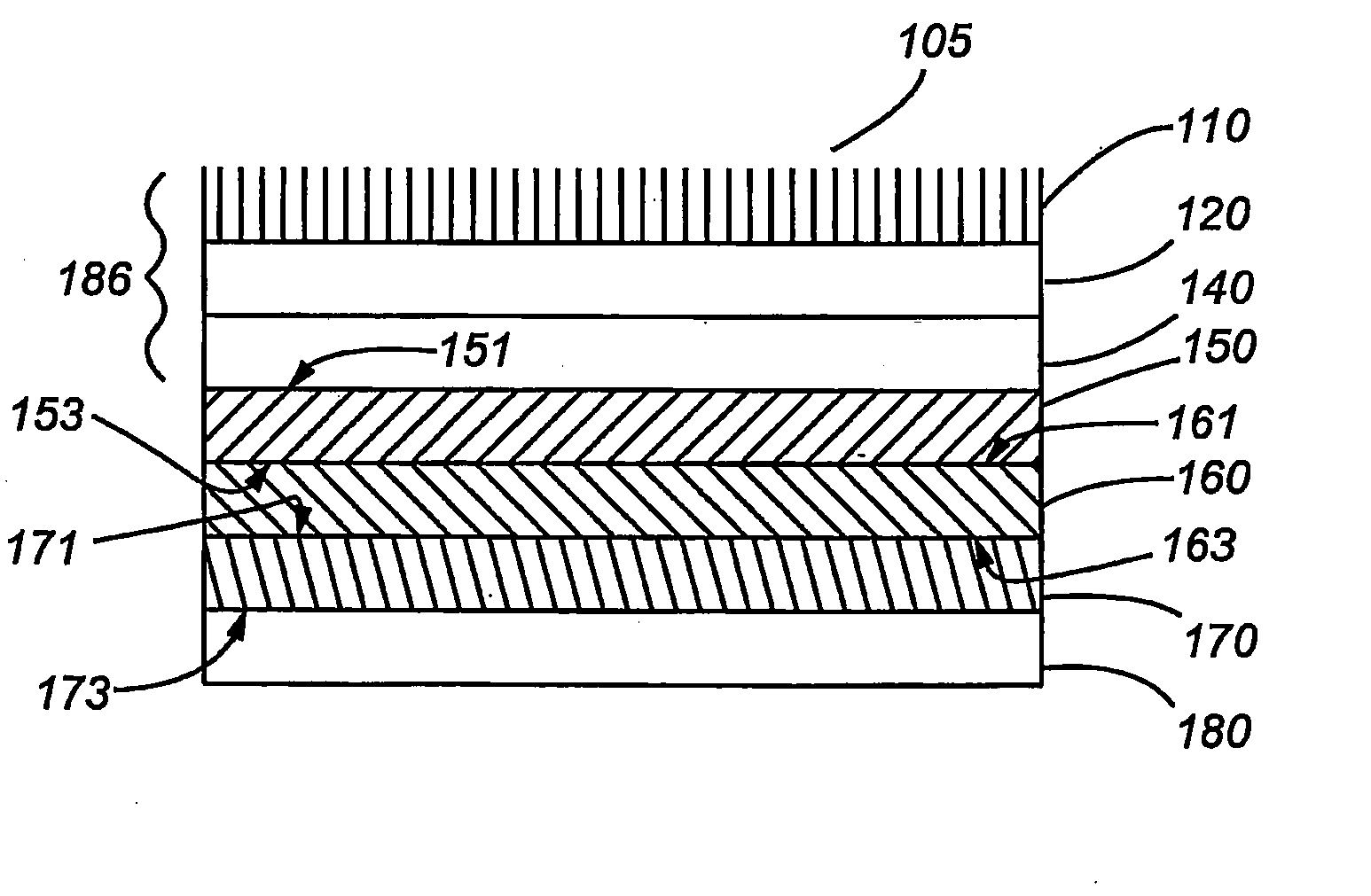
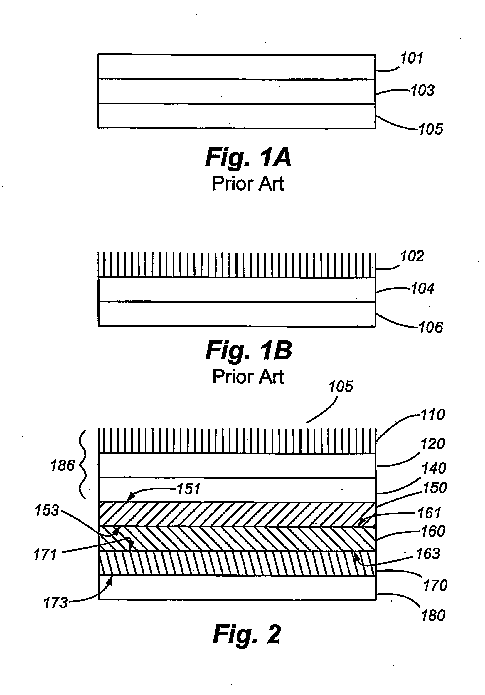
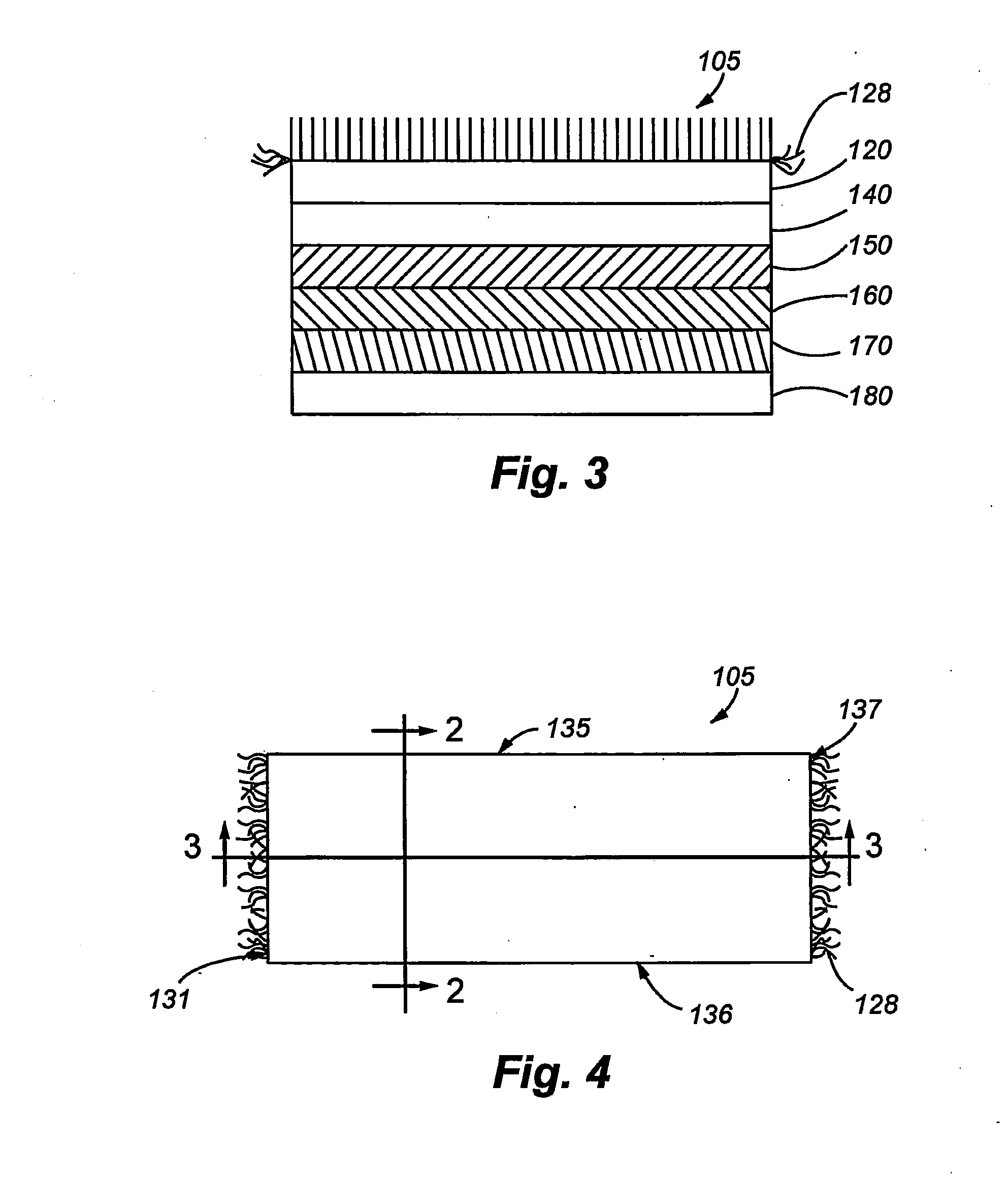
[0022]A first rigid mouse pad embodiment is shown in FIGS. 2-4. The rigid mouse pad article 105 comprises a flock assembly 186, a rigid sheet material 160 having a first side 161 and a second opposing side 163, a first adhesive layer 150 positioned between the flock assembly 186 and the first side 161 of the rigid sheet material 160 and a second adhesive layer 170 positioned between the second opposing side 163 of the rigid sheet material 160 and a non-slip material 180. The flock assembly 186 includes a third adhesive layer 120 positioned between a plurality of flock fibers 110 and a resilient layer 140. Referring to FIG. 4, the rigid mouse pad surface is substantially rectangular, having longer sides 135 and 136 and shorter sides 131 and 137. The mouse pad 105 can have fringe 128 added to the shorter sides 131 and 137 and / or longer sides 135 and 136 for aesthetic reasons. If used, is preferred to add fringe 128 at the interface of the flock fibers 110 and the resilient layer 140.

[...


PUM


Abstract

In one embodiment, the invention relates to a rigid computer mouse pad having a flocked “mousing” surface and a non-slip underside. The non-slip underside can be a second flocked surface.

Description

CROSS REFERENCE TO RELATED APPLICATIONS[0001]The present application claims benefits of U.S. Provisional Patent Application Ser. No. 60 / 865,785, filed Nov. 14, 2006, and U.S. Provisional Patent Application Ser. No. 60 / 869,671, filed Dec. 12, 2006 both to Abrams, each of which is incorporated herein by reference.FIELD OF THE INVENTION[0002]The invention relates generally to flocked articles, particularly to rigid, flocked articles. More particularly the invention relates to rigid mouse pad articles having a flocked “mousing surface” and a non-slip underside. In one particular embodiment, the non-slip material is a second flocked surface.BACKGROUND OF THE INVENTION[0003]A computer mouse has become a standard computer peripheral, typically positioned and operated on a work surface as a point and command entering device, which controls with a relatively high level of precision the movement of a cursor over a computer monitor display screen. For instance, commands are entered by position...

Claims


Application Information

Patent Timeline
Patent Type & Authority Applications(United States)
IPC IPC(8): G06F3/039
CPCG06F3/0395
Inventor ABRAMS, LOUIS BROWN
Owner HIGH VOLTAGE GRAPHICS
Why Eureka
Try Eureka