Eureka AIR delivers breakthrough ideas for toughest innovation challenges, trusted by R&D personnel around the world.

Relay connector

Active Publication Date: 2008-05-15
YOKOWO CO LTD
View PDF7 Cites 2 Cited by
  • Summary
  • Abstract
  • Description
  • Claims
  • Application Information

AI Technical Summary

Benefits of technology

[0006] It is therefore an object of the invention to a relay connector for bringing probes into contact with an connector to be inspected, in which a distance between the probes can be adjusted according to a distance between terminals arranged in two rows on the connector to be inspected.
[0011] The first pin block may be formed with an insertion hole into which the second pin block is inserted so as to move only in a direction in which the first and second pin blocks approaches and separates with respect to each other, a position of the second pin block may be adjusted in a state that the second pin block is inserted into the insertion hole, and a positioning pin perpendicular to the direction may be inserted into the second pin block by passing through a wall of the insertion hole from outside of the insertion hole, whereby the second pin block is fixed to the first pin block.
[0011] The first pin block may be formed with an insertion hole into which the second pin block is inserted so as to move only in a direction in which the first and second pin blocks approaches and separates with respect to each other, a position of the second pin block may be adjusted in a state that the second pin block is inserted into the insertion hole, and a positioning pin perpendicular to the direction may be inserted into the second pin block by passing through a wall of the insertion hole from outside of the insertion hole, whereby the second pin block is fixed to the first pin block.

Problems solved by technology

Provided that the jig-side connector is fixed to a jig-side board by soldering, and a number of wiring cables connected to the measuring instrument are soldered to the jig-side board, it is difficult to exchange only the jig-side connector.
Therefore, the whole unit of the jig-side connector, the jig-side board, and the wiring cables must be exchanged inevitably.
Consequently, there occurs such inconvenience that cost for measuring and inspection is increased.
However, this is not absolutely satisfactory.

Method used


Image

  • Relay connector
  • Relay connector
  • Relay connector

Examples


first embodiment

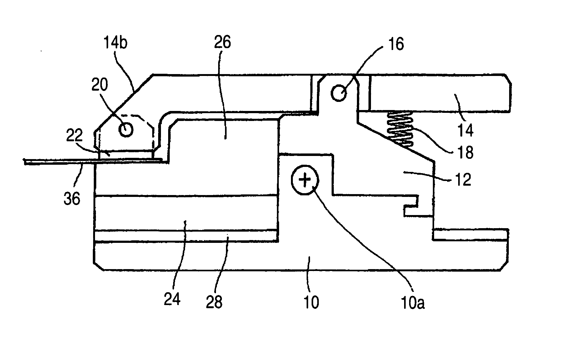
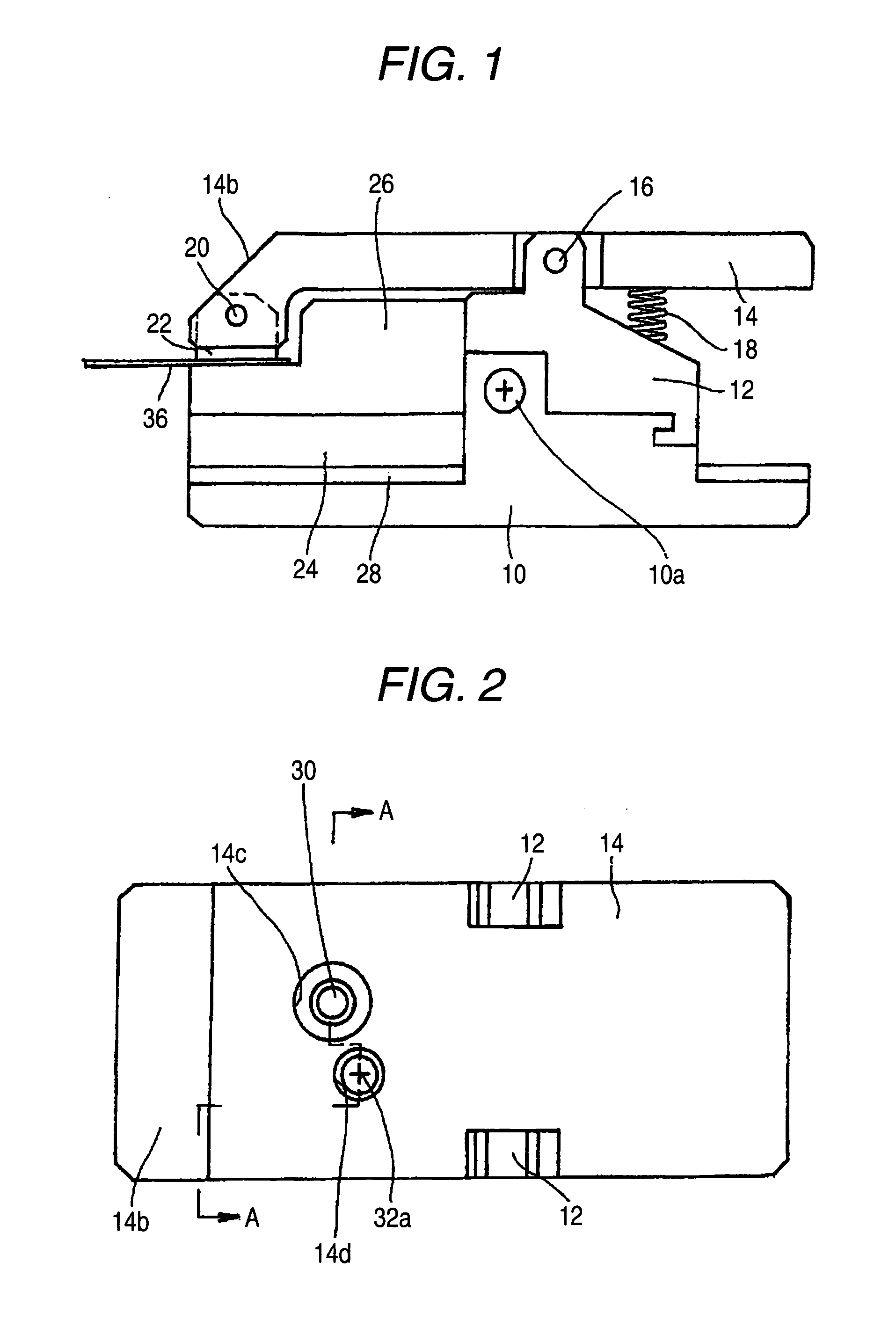
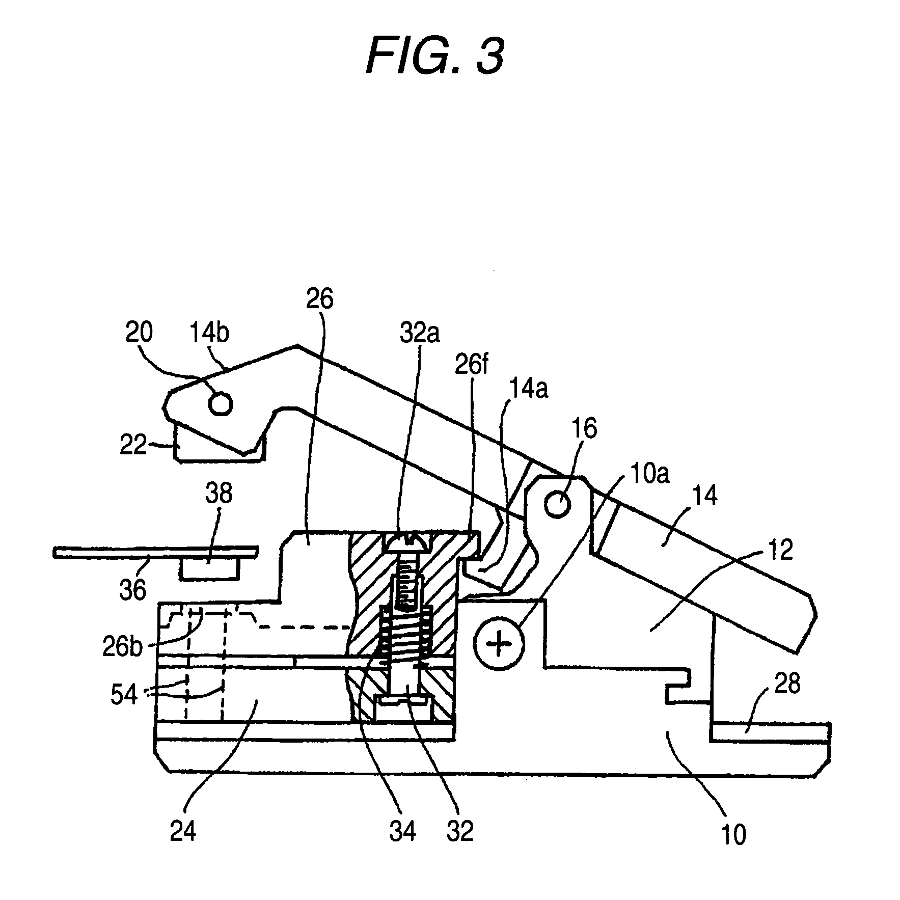
[0028] Now, the invention will be described referring to FIGS. 1 to 14.

[0029] In FIGS. 1 to 14, a relay connector in the first embodiment of the invention is constructed in the following manner. As a first step, a hinge member 12 is fixed to a base member 10 with a screw 10a. A pressure operating member 14 is provided on this hinge member 12 so as to swing by means of a swing shaft 16 which is passed through the pressure operating member 14. A compression spring 18 is provided in a contracted state between a rear part of the pressure operating member 14 and the hinge member 12. Moreover, a pressure block 22 is provided at a distal end side of the pressure operating member 14 so as to swing by means of a second swing shaft 20 which is passed through the operating member 14 in parallel with the swing shaft 16. In addition, a floating guide 26 formed of insulating material is arranged on a pin block 24 formed of insulating material so as to approach and separate with respect to each ot...


PUM


Abstract

A relay connector electrically connects terminals which are arranged in two rows on a connector to be inspected provided on a board for inspection to a measuring instrument. The relay connector includes first probes, mounted on a first pin block so as to be contacted with one row of the terminals arranged on the connector to be inspected, and second probes, mounted on a second pin block so as to be contacted with the other row of the terminals arranged on the connector to be inspected. The first and second pin blocks can approach and separate with respect to each other and a distance between the first and second pin blocks can be adjusted and fixed, so that the first and second probes are respectively contacted with the terminals which are arranged in two rows on the connector to be inspected.

Description

BACKGROUND OF THE INVENTION [0001] The present invention relates to a relay connector to be used for electrically connecting a connector to be inspected which is arranged on an inspection board for an electronic component or the like, to a measuring instrument. [0002] In some of compact electronic devices such as a mobile phone and a digital camera, a plurality of boards are superposed on one another for the purpose of mounting many electronic circuits in a small space, and these boards are electrically connected by way of connectors which are respectively provided thereon. In order to inspect the boards and the connectors provided thereon, it has been conducted to electrically connect a measuring instrument or the like to the connectors by appropriate means. In order to inspect a whole unit of the board to be inspected and the connector to be inspected, it is desirable that the connector to be inspected is engaged with a jig-side connector to be mated, and then, they are electrical...

Claims


Application Information

Patent Timeline
IPC IPC(8): H01R12/00
CPCG01R1/0416G01R31/2801H01R29/00H01R31/06G01R1/067G01R1/07364H01R43/00G01R31/66
Inventor SUZUKI, HISASHIHIRAKO, RYOICHI
Owner YOKOWO CO LTD
Why Eureka
Eureka Blog
Learn More