Control system for prosthetic knee

a control system and prosthetic knee technology, applied in the field of prosthetic knees, can solve the problems of lack of adaptiveness, time-consuming methodology for programming a prosthetic knee, and inability to compensate for unforeseen changes in the patient's or the patient's environmen

Inactive Publication Date: 2008-05-15
MASSACHUSETTS INST OF TECH
View PDF0 Cites 104 Cited by
  • Summary
  • Abstract
  • Description
  • Claims
  • Application Information

AI Technical Summary

Benefits of technology

[0008]Accordingly it is one advantage of the present invention to overcome some or all of the above limitations by providing an automated speed-adaptive and patient-adaptive control scheme and system for a knee prosthesis. The control scheme and system utilizes sensory information measured local to the prosthesis to automatically adjust stance and swing phase knee resistances to a particular wearer under a wide variety of locomotory activities. Advantageously, no patient-specific information needs to be pre-programmed into the prosthetic knee by a prosthetist or the patient. The system is able to adapt to various types of disturbances once the patient leaves the prosthetist's facility because it is patient-adaptive and speed-adaptive.
[0009]In accordance with one preferred embodiment, a method is provided of adaptively controlling the stance phase damping of a prosthetic knee worn by a patient. The method comprises the step of providing a memory in the prosthetic knee. The memory has stored therein correlations between sensory data and stance phase damping established in clinical investigations of amputees of varying body size. Instantaneous sensory information is measured using sensors local to the prosthetic knee as the patient stands, walks or runs. The instantaneous sensory information is used in conjunction with the correlations to automatically adjust stance phase damping suitable for the patient without requiring patient specific information to be pre-programmed in the prosthetic knee.
[0010]In accordance with another preferred embodiment, a method is provided of adaptively controlling the swing phase damping torque of a prosthetic knee worn by a patient as the patient travels at various locomotory speeds. The ground contact time of a prosthetic foot connected to the prosthetic knee by a prosthetic leg is indicative of the locomotory speed of the patient. The method comprises the step of continuously measuring the contact time over periods of one gait cycle as the patient ambulates at various locomotory speeds. The contact time is stored within a memory of the prosthetic knee in time slots corresponding to the locomotory speed of the patient. The swing phase damping for knee flexion is iteratively modulated to achieve a target peak flexion angle range until the flexion damping converges within each time slot. The swing phase damping for knee extension is iteratively modulated to control the impact force of the extending prosthetic leg against an artificial knee cap of the prosthetic knee until the extension damping converges within each time slot. The converged damping values are used to automatically control swing phase damping at all locomotory speeds.
[0011]In accordance with one preferred embodiment, an adaptive prosthetic knee is provided for controlling the knee damping torque during stance phase of an amputee. The prosthetic knee generally comprises a controllable knee actuator, sensors and a controller. The knee actuator provides a variable damping torque in response to command signals. The sensors measure the force and moment applied to the prosthetic knee as the amputee moves over a supporting surface. The controller has a memory and is adapted to communicate command signals to the knee actuator and receive input signals from the sensors. The memory has stored therein relationships between sensory data and stance phase damping established in prior clinical investigations of patients of varying body size. The controller utilizes sensory data from the sensors in conjunction with the relationships to adaptively and automatically control the damping torque provided by the knee actuator during stance phase independent of any prior knowledge of the size of the amputee.
[0012]For purposes of summarizing the invention, certain aspects, advantages and novel features of the invention have been described herein above. Of course, it is to be understood that not necessarily all such advantages may be achieved in accordance with any particular embodiment of the invention. Thus, the invention may be embodied or carried out in a manner that achieves or optimizes one advantage or group of advantages as taught herein without necessarily achieving other advantages as may be taught or suggested herein.
[0013]All of these embodiments are intended to be within the scope of the invention herein disclosed. These and other embodiments of the present invention will become readily apparent to those skilled in the art from the following detailed description of the preferred embodiments having reference to the attached figures, the invention not being limited to any particular preferred embodiment(s) disclosed.

Problems solved by technology

Disadvantageously, such a methodology for programming a prosthetic knee is time consuming for both the prosthetist and the patient and has to be repeated for each patient.
Moreover, any unforeseen changes in the patient or in the patient's environment are not compensated for by the knee prosthesis after the patient has left the prosthetist's facility.
This lack of adaptiveness in the knee system can disrupt normal locomotion and render the pre-programmed knee uncomfortable or even unsafe.
Again, undesirably this results in additional wastage of time and further adds to the cost.

Method used


Image

  • Control system for prosthetic knee
  • Control system for prosthetic knee
  • Control system for prosthetic knee

Examples


Embodiment Construction

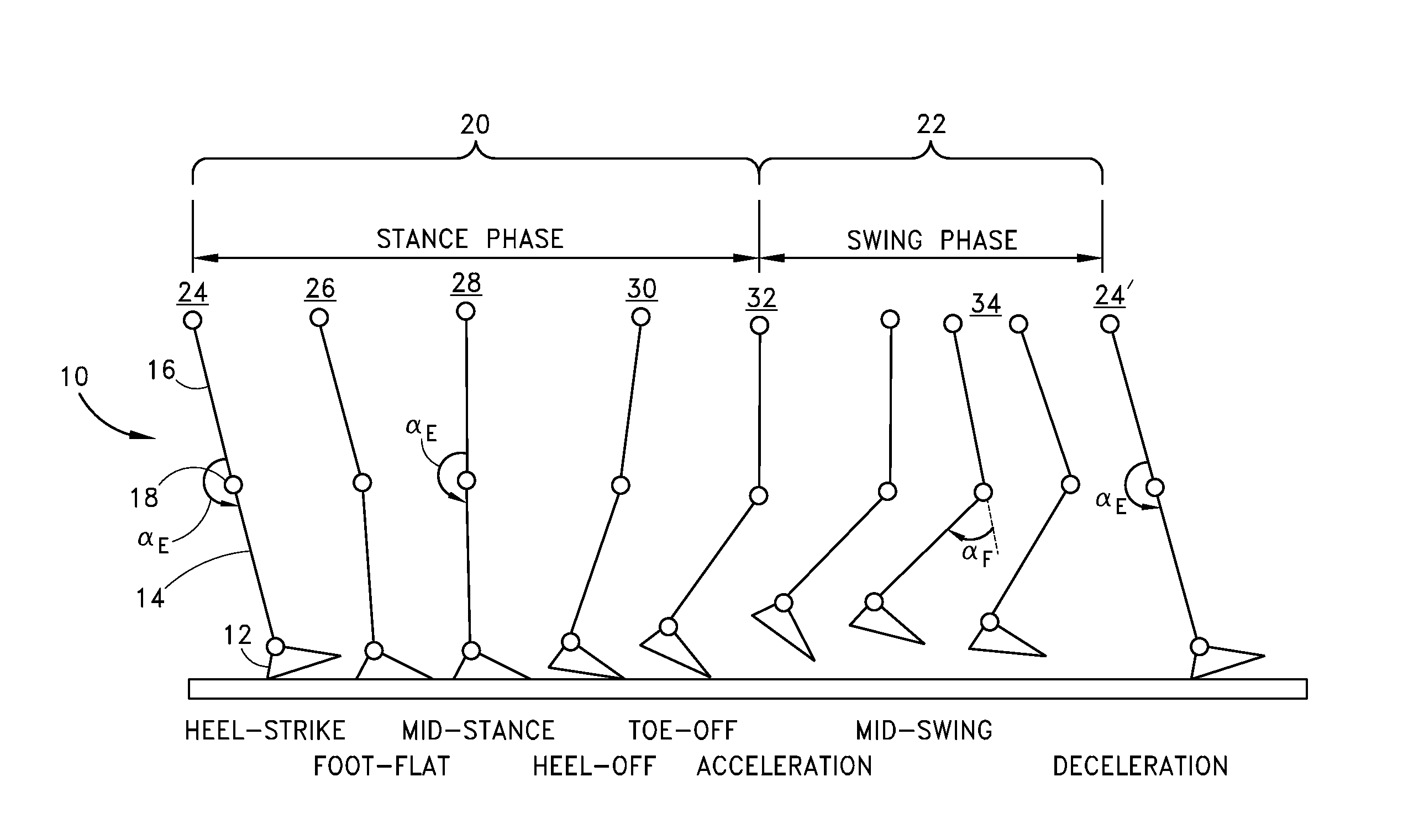
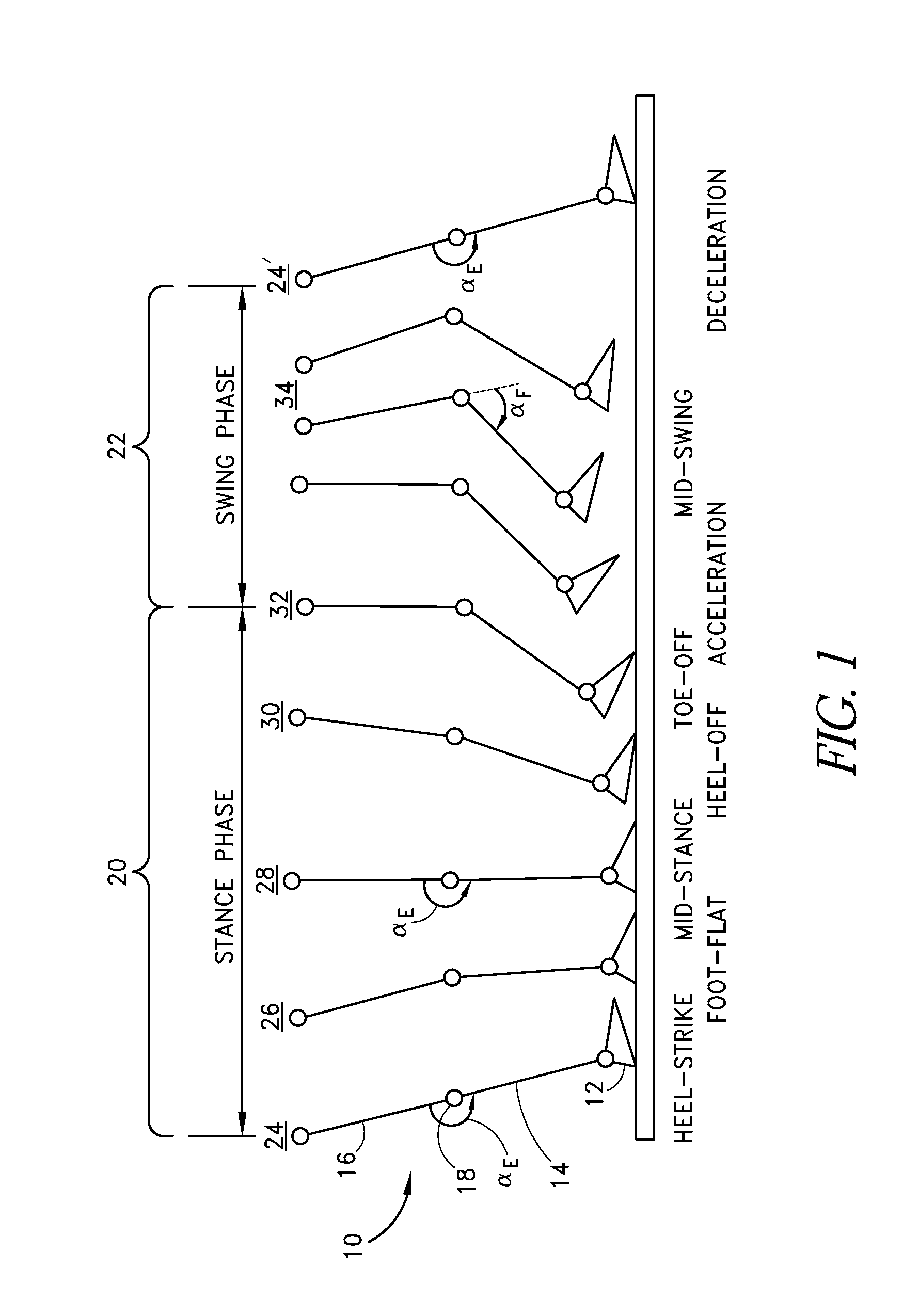
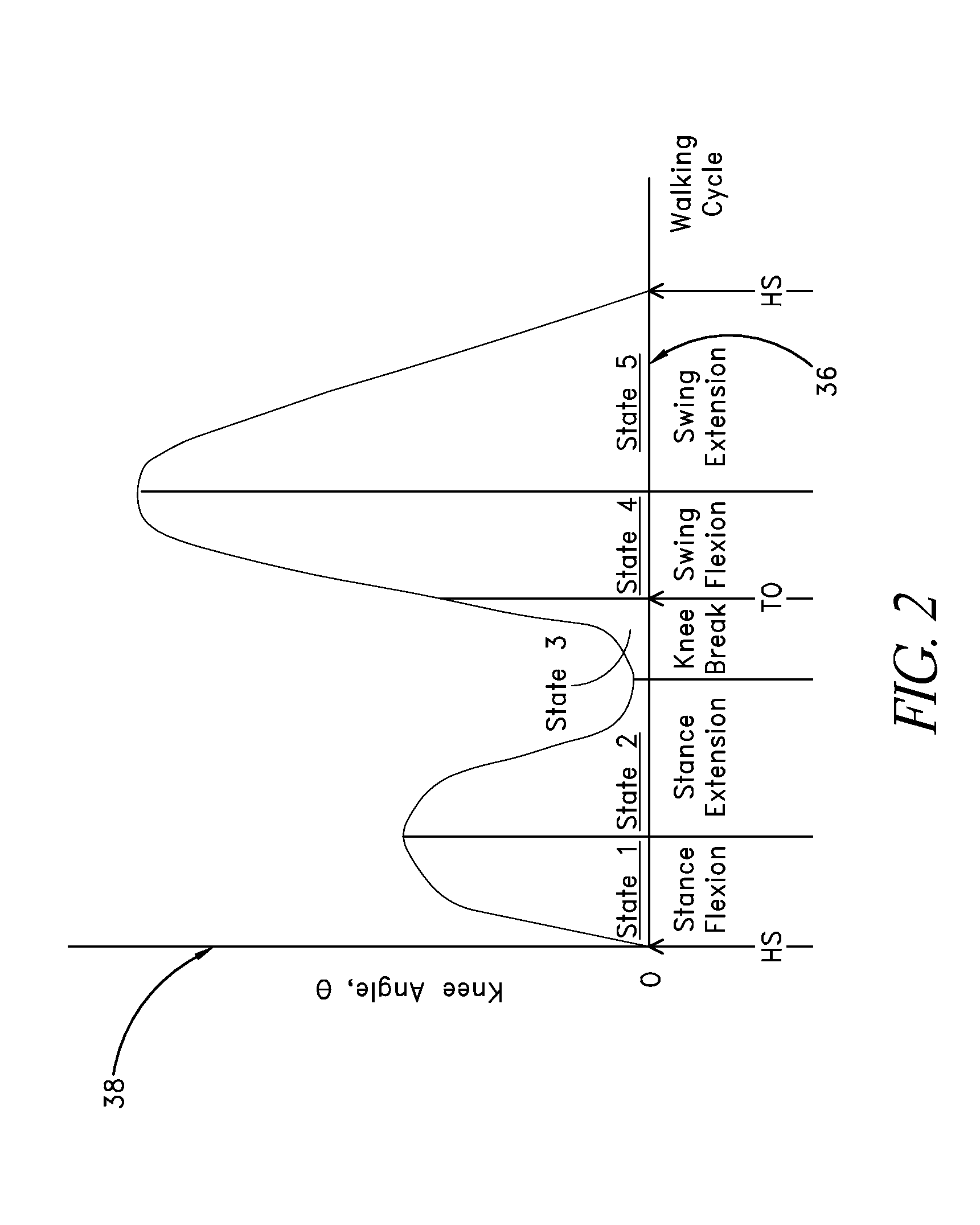
[0025]In order for a trans-femoral (above-knee) amputee to walk in a variety of circumstances, a prosthetic knee should provide stance control to limit buckling when weight is applied to the limb. In addition, a prosthesis should provide swing phase control so that the knee reaches full extension just prior to heel strike in a smooth and natural manner.

[0026]Unlike a biological knee, a prosthetic knee should accomplish both stance and swing control without direct knowledge of its user's intent or of the environment. Rather, a prosthetic knee has to infer whether the amputee is walking, running, or sitting down. It should also determine when subtle or drastic changes occur in the environment, such as when the user lifts a suitcase or walks down a slope. Still further, the prosthesis should move naturally and be safe at all locomotory speeds, and should perform equally well for all amputees, independent of body weight, height, or activity level, without requiring patient-specific info...


PUM


Abstract

The invention relates to an automated speed-adaptive and patient-adaptive control scheme and system for a knee prosthesis. The control scheme and system utilizes sensory information measured local to the prosthesis to automatically adjust stance and swing phase knee resistances to a particular wearer under a wide variety of locomotory activities. Advantageously, no patient-specific information needs to be pre-programmed into the prosthetic knee by a prosthetist or the patient. The system is able to adapt to various types of disturbances once the patient leaves the prosthetist's facility because it is patient-adaptive and speed-adaptive.

Description

RELATED APPLICATIONS[0001]This application is a continuation of U.S. application Ser. No. 10 / 646,097, filed Aug. 22, 2003, now U.S. Pat. No. 7,279,009 B2, issue date Oct. 9, 2007, which is a continuation of U.S. application Ser. No. 09 / 823,931, filed Mar. 29, 2001, now U.S. Pat. No. 6,610,101 B2, issue date Aug. 26, 2003, which claims the benefit of U.S. Provisional Application No. 60 / 192,966, filed Mar. 29, 2000, the entirety of each one of which is hereby incorporated by reference herein.BACKGROUND OF THE INVENTION [0002]1. Field of the Invention[0003]The present invention relates to prosthetic knees in general and, in particular, to a speed-adaptive and patient-adaptive control scheme and system for an external knee prosthesis.[0004]2. Description of the Related Art[0005]Most conventional active knee prostheses are variable torque brakes where joint damping is controlled by a microprocessor as an amputee walks from step to step. Many brake technologies have been employed for knee...

Claims


Application Information

Patent Timeline
Patent Type & Authority Applications(United States)
IPC IPC(8): A61B5/103A61F2/38A61F2/48A61F2/50A61F2/64A61F2/68A61F2/70A61F2/76F16F9/53
CPCA61B5/1038A61B5/4528A61F2/64A61F2/68A61F2002/5003F16F9/535A61F2002/6818A61F2002/704A61F2002/7625A61F2002/7635A61F2002/7645A61F2002/5004A61F2/70A61F2/74
Inventor HERR, HUGH M.WILKENFELD, ARIBLECK, OLAF
Owner MASSACHUSETTS INST OF TECH
Why Eureka
Try Eureka