
Pressure-compensated, subsea chemical injection valve

a technology of chemical injection valve and pressure compensation, which is applied in the field of valves, can solve the problems of not being able to compensate for hydrostatic pressure, not being able to prevent backflow through the valve, and not being able to meet the requirements of use in the subsea environment, so as to facilitate manufacture and facilitate replacement of the valve sea

Active Publication Date: 2008-05-22
NAT COUPLING
View PDF14 Cites 5 Cited by
  • Summary
  • Abstract
  • Description
  • Claims
  • Application Information

AI Technical Summary

Benefits of technology

[0013]The valve seat protrudes into the axial passage and engages a shoulder on the carrier to limit axial travel of the carrier in the direction of extension of the load spring(s), whereby the seal disc may be normally positioned over the valve seat to prevent flow through the lateral passage. Sufficient fluid pressure at the valve inlet, however, will cause the carrier to move in a direction which compresses the load spring(s), thereby unseating the seal disc and opening the valve.
[0014]To facilitate manufacture and to enable easy replacement of the valve seat, the body may be made in three parts including a main part, an outlet part and a pressure compensation part, the parts being held together by threaded engagement.

Problems solved by technology

The valve described in U.S. Pat. No. 4,456,028 is not suitable for use in the subsea environment.
It requires manual adjustment for setting the opening pressure and does not compensate for the hydrostatic pressure.
Moreover, it has no means for preventing backflow through the valve if, for any reason, the outlet pressure exceeds the inlet pressure.

Method used


Image

  • Pressure-compensated, subsea chemical injection valve
  • Pressure-compensated, subsea chemical injection valve
  • Pressure-compensated, subsea chemical injection valve

Examples


Embodiment Construction

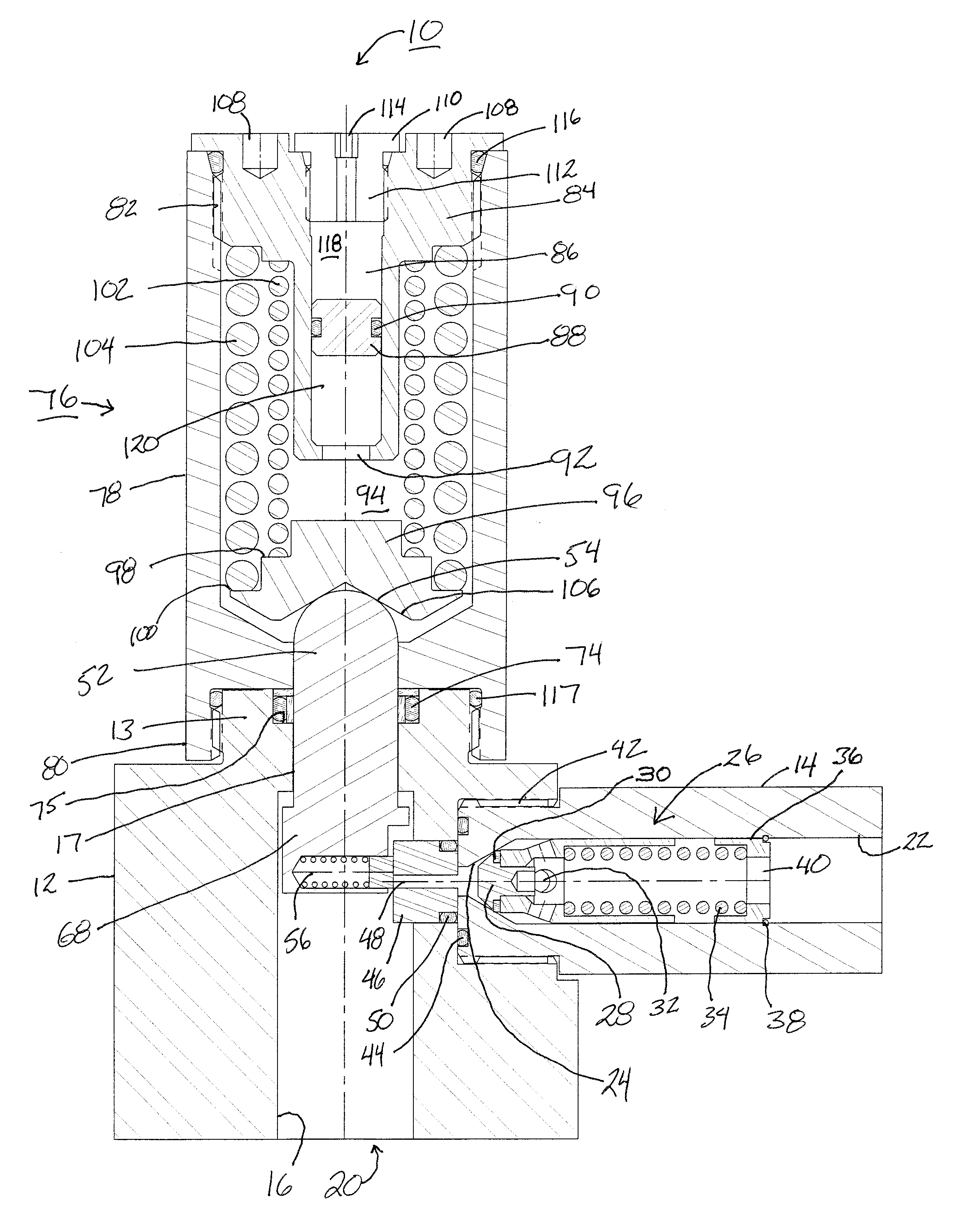
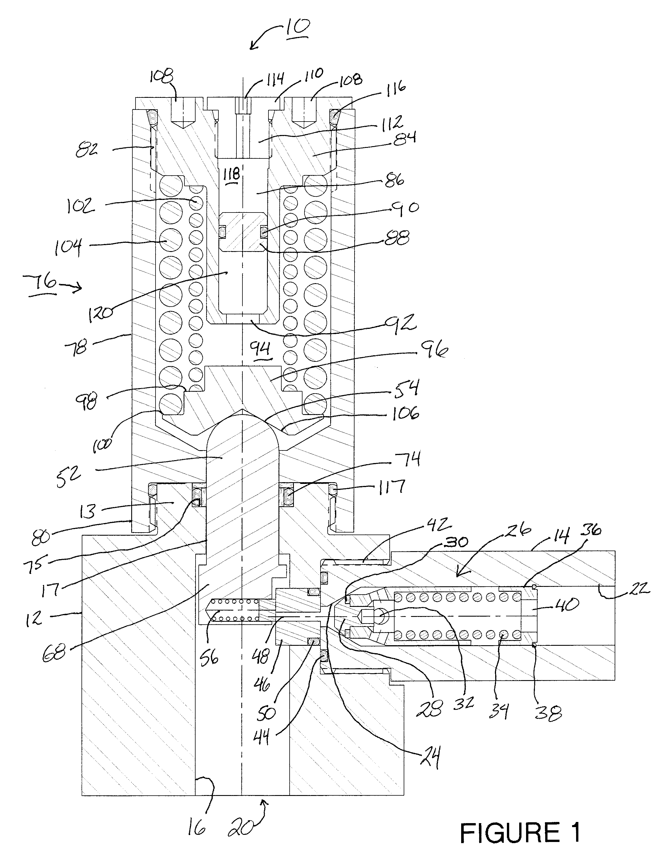
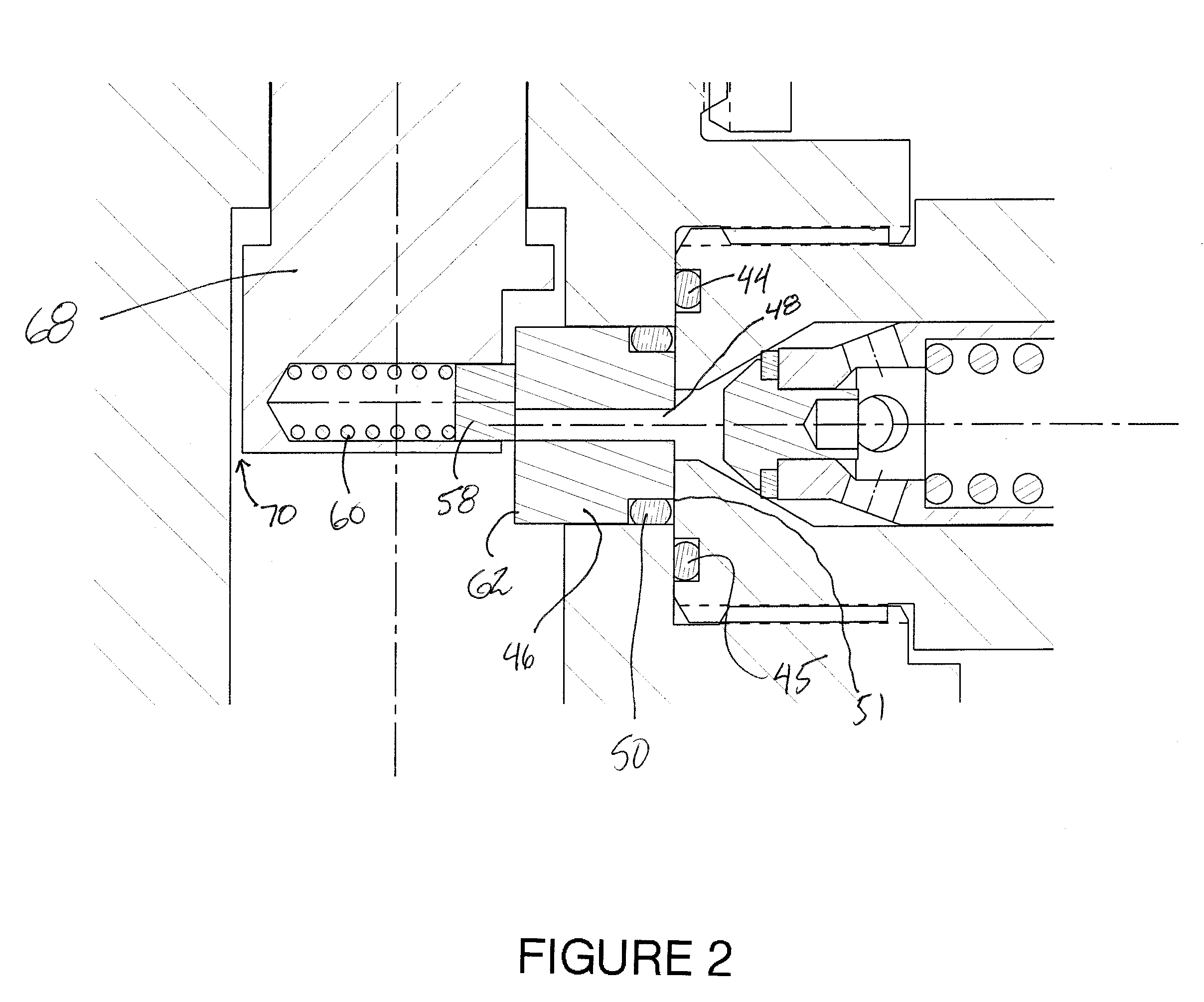
[0017]Referring now to the drawings and more particularly to FIG. 1, there is shown a valve 10 comprising a main body part 12, an outlet body part 14 and a pressure compensator 76. The three body parts may be generally rectangular parallelepipeds secured together by threaded engagement. Seal 44 which may be an O-ring seal received in an annular groove 45 in one side of body part 14 seals with the adjacent side of body part 12.

[0018]A cylindrical bore provides an axial passage 16 in body part 12. The passage has an inlet 20 at one end which may be adapted to make a connection with a pipe or other conduit leading to a fluid reservoir or line whose pressure may be limited by valve 10.

[0019]A cylindrical bore 22 in the outlet part 14 of valve 10 provides a lateral passage in the body. This passage at its outer end provides an outlet 18 which, by way of example, may be adapted to make a fluid connection with a conduit leading to a subsea well. The passage further includes transverse cyli...


PUM


Abstract

A backpressure-protected valve suitable for subsea well treatment chemical injection applications includes an improved gate valve, a check valve and a pressure compensator responsive to ambient hydrostatic pressure. The check valve may comprise a poppet valve in a detachable outlet body. The pressure compensator comprises a free piston in a cylinder. The portion of the cylinder on one side of the piston is exposed to seawater whereas the portion of the cylinder on the opposing side of the piston is filled with a selected hydraulic fluid. In this way the valve actuator is not exposed to the corrosive and / or contaminating effects of seawater.

Description

CROSS-REFERENCE TO RELATED APPLICATIONS[0001]NoneSTATEMENT REGARDING FEDERALLY SPONSORED RESEARCH OR DEVELOPMENT[0002]NoneBACKGROUND OF THE INVENTION[0003]1. Field of the Invention[0004]This invention relates to valves. More particularly, it relates to pressure-compensated valves adapted for use in the subsea environment.[0005]2. Description of the Related Art[0006]U.S. Pat. No. 4,456,028 discloses a relief gate valve that comprises a hollow body having an inlet and an outlet, a seat ring in the outlet having a face adapted to engage a gate, a closure mounted for movement relative to the seat ring and including a carrier having a passage therethrough in which are slidably disposed a lipped gate disc adapted to engage the seat face and block the outlet when the valve is in closed position, a pressure spring pressing the gate disc against the seat face when the valve is in closed position, and a ball transferring the reaction of the spring to the body. The closure further includes a s...

Claims


Application Information

Patent Timeline
Patent Type & Authority Applications(United States)
IPC IPC(8): F16K31/12
CPCF16K17/046Y10T137/2036Y10T137/1939Y10T137/7781Y10T137/7792
Inventor WATSON, RICHARD R.
Owner NAT COUPLING
Learn More