Device for absorption of impact energy on an automobile

a technology for absorbing energy and automobiles, applied in the direction of shock absorbers, elastic dampers, bumpers, etc., can solve the problems of relatively high weight of such systems, large installation space requirements, and relatively high system costs, and achieve the effect of cost-effective manufacturing and simple design

Inactive Publication Date: 2006-01-19
ZF FRIEDRICHSHAFEN AG
View PDF1 Cites 3 Cited by
  • Summary
  • Abstract
  • Description
  • Claims
  • Application Information

AI Technical Summary

Benefits of technology

[0007] It is the object of the invention to provide a device for absorbing the impact energy imparted on the vehicle, wherein the device is suitable for different driving and danger situations, has a simple design, and can be manufactured cost-effectively.
[0010] According to an advantageous embodiment of the invention, the actuator is operated exclusively based on sensor signals, regardless of the other driving situation or driving speed. This is accomplished by blocking movement of the force introduction element with the actuator, or with the position of the actuator, if the sensors detect an impending collision of the vehicle with another vehicle or with a stationary obstacle. However, if the sensors and an associated processing electronics recognize a potential collision of the vehicle with a living being, for example a pedestrian, then the actuator is activated to allow the force introduction element to move. The impact force on the pedestrian is thereby reduced, because the kinetic energy is not directly, i.e., “hard”, converted into deformation work during impact, but initially transferred to the force introduction element which moves in the direction of the deformation element. This reduces the risk of injury or the severity of injuries sustained during impact. It should be mentioned at this point that recognition by sensors and processing of sensor signals for predicting the type of impact is not the subject of the present invention. Corresponding systems have already being developed, or improvements for such systems are currently in the development stage. It should also be noted that the terms deformation element and distortion element will in the following be used synonymously.
[0014] According to a practical embodiment, the device includes two tubular energy absorbers, each of which is mounted on a longitudinal vehicle support in the end section of a bumper with its longitudinal axis extending in the direction of the longitudinal vehicle support. Each of the energy absorbers has a guide tube receiving the deformation element, and further the cup-shaped force introduction element, as well as other energy absorber components. According to one embodiment, the force introduction element is movably guided on the outer periphery of a hollow-cylindrical guide element having recesses, and the shaft of an actuator which can be controlled depending on the driving situation extends through the deformation element. The aforementioned shaft extends into the guide element and has an eccentrically shaped a free end. The position of the eccentric element can be changed by the actuator in the circumferential direction and determines the radial position of at least two wings which are arranged inside the guide element perpendicular to the longitudinal axis of the energy absorber. In one position of the eccentric element, the wings are urged radially outwardly into the recesses of the guide element, so as to prevent the force introduction element connected with the bumper from moving. Conversely, in the other position of the eccentric element, the wings move radially inwardly by following the contour of the eccentric element and can move freely in the region of the recesses. This unobstructed motion enables limited axial travel of the force introduction element on the guide element in the direction of the deformation element.

Problems solved by technology

However, such systems are relatively expensive and tend to require installation space which is unavailable in many typical applications.
Disadvantageous is also the relatively high weight of such systems.
Problematic with this and comparable systems is, for example, that the absorption characteristic is the same, regardless if a vehicle equipped in this manner collides with another vehicle, a stationary obstacle, or with a pedestrian.
Pedestrians can therefore be seriously injured in such situations.
Nevertheless, the solution is hardly suitable to prevent fractures in the lower leg, because these are auxiliary measures which are less intended to affect the manner in which the impact energy is dissipated, but rather attempt to remove the body of an affected pedestrian from the immediate danger zone on a predetermined trajectory in the event of an impact.
However, the impact energy has then already affected the knee or the lower leg of the pedestrian.

Method used


Image

  • Device for absorption of impact energy on an automobile
  • Device for absorption of impact energy on an automobile
  • Device for absorption of impact energy on an automobile

Examples


Embodiment Construction

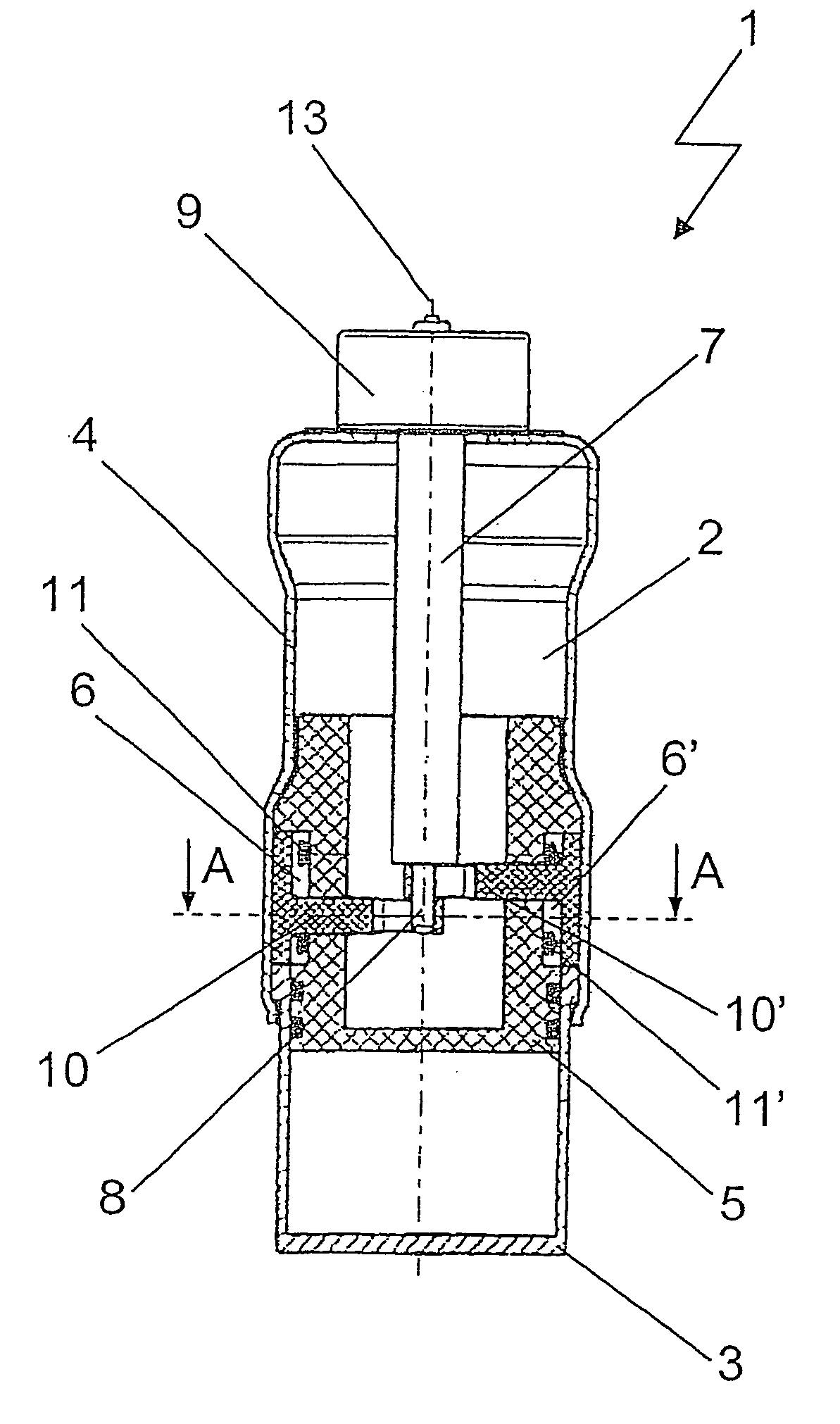
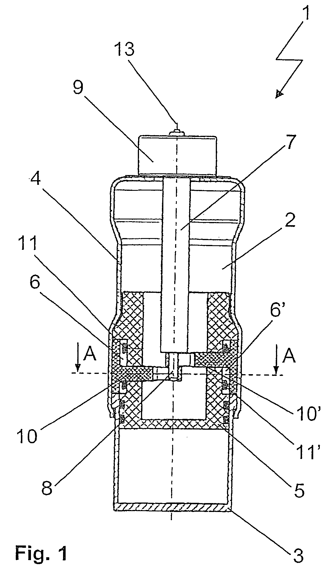
[0020]FIG. 1 shows the essential element of the device of the invention, namely the switchable energy absorber 1, or impact absorber. The axially upper end (as seen in the drawing) of the absorber 1, shown here in an axial cross-sectional view, is connected with the longitudinal support (not shown) of a vehicle, whereas the axially lower end is connected with a bumper (also not shown). Preferably, two of these energy absorbers are arranged between the bumper and the vehicle chassis.

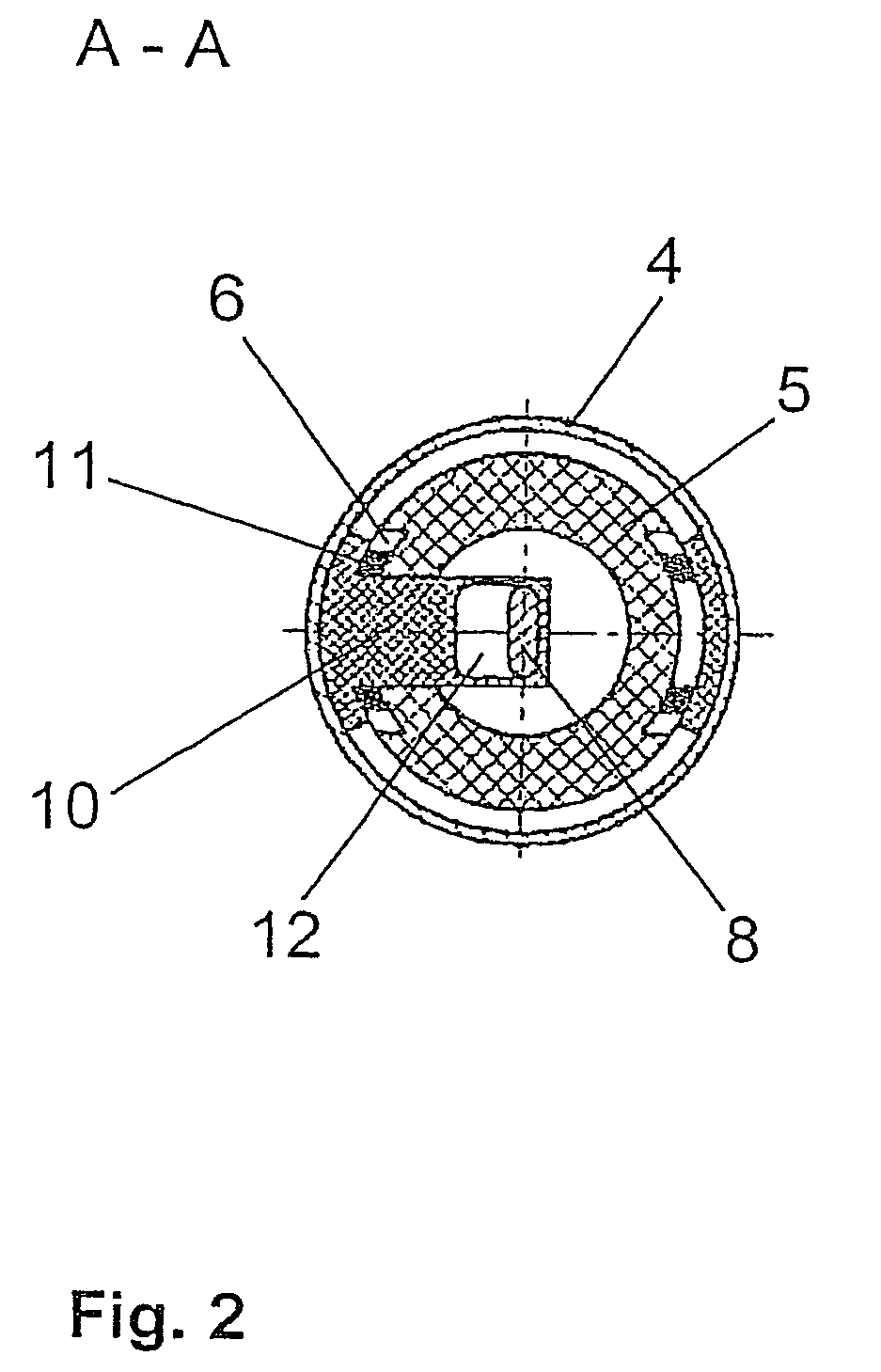
[0021] The energy absorber 1 includes a guide tube 4 which receives the deformation element 2 or distortion element, the force introduction element 3, as well as a guide element 5 with recesses 6, 6′ disposed on the outer circumference and wings 10, 10′ supported in the region of the recesses 6, 6′. The deformation element 2, which can be implemented as a deformation piston made of glass-fiber reinforced plastic material, is penetrated by the shaft 7 of an actuator 9. The motor shaft 7 extends into the g...


PUM


Abstract

A device for absorption of impact energy on an automobile is provided, with at least one energy absorber arranged between a bumper and the vehicle chassis, which has a deformation element which deforms in the event of a collision. The device adapts to different driving and risk situations and which has a simple design and can be manufactured cost-effectively. The absorption characteristic of the energy absorber is implemented to adapt to the driving situation. This is achieved by transferring the impact energy to the deformation element inside the energy absorber via at least one force introduction element which, depending on the respective driving situation, either transfers the impact energy directly to the deformation element for conversion into deformation work, or initially performs an excursion-limited motion inside the energy absorber and only thereafter transfers the impact energy to the deformation element for conversion into deformation work.

Description

BACKGROUND OF THE INVENTION [0001] 1. Field of the Invention [0002] The present invention relates to a device for absorption of impact energy on an automobile, with at least one energy absorber arranged between a bumper and the vehicle chassis. More particularly, the invention relates to devices of this type, wherein the energy absorber has a deformation element which deforms in the event of a collision, whereby the energy imparted on the vehicle during the collision is at least partially converted by the deformation into deformation work. [0003] 2. Description of the Related Art [0004] Several different solutions are already known for transferring kinetic energy generated during a collision of a vehicle to chassis via the bumper. More particularly, energy absorption systems are generally differentiated in that the elements change reversibly or an irreversibly during impact. The first category includes, for example, systems which dissipate the kinetic energy transferred to to the ve...

Claims


Application Information

Patent Timeline
Patent Type & Authority Applications(United States)
IPC IPC(8): B60R19/26B60R21/34
CPCB60R19/36B60R2021/346B60R2019/268B60R2019/262
Inventor STEINBACH, GUIDOWORMS, STEFAN
Owner ZF FRIEDRICHSHAFEN AG
Why Eureka
Try Eureka