Device For Closing A Container Including Improved Secure Closure Means

Active Publication Date: 2016-08-18
NEMERA LA VERPILLIERE SAS
View PDF3 Cites 0 Cited by
  • Summary
  • Abstract
  • Description
  • Claims
  • Application Information

AI Technical Summary

Benefits of technology

The patent describes a closure device for containers that prevents accidental manipulation by children. The device includes an internal cap member with a security element that moves from a cooperation position to a separation position when the external cap member is moved. The device also includes resistance means to prevent unintentional separation of the internal cap member from the container. This prevents the risk of the closure device being opened if a child tries to press the external cap member against a surface.

Problems solved by technology

The drawback is that a child can also easily access the dispensing tip and therefore the contents of the reservoir, which may be hazardous in some cases.
These means are often difficult to use, however, and often require a relatively high physical force.

Method used


Image

  • Device For Closing A Container Including Improved Secure Closure Means
  • Device For Closing A Container Including Improved Secure Closure Means
  • Device For Closing A Container Including Improved Secure Closure Means

Examples


first embodiment

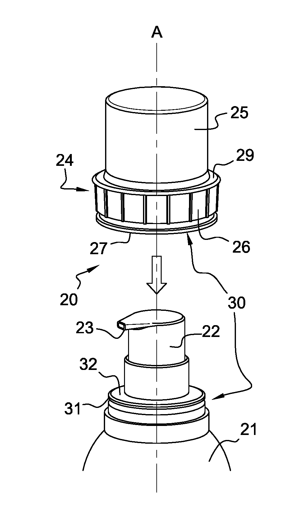
[0072]The medical device 20 also includes a device 24 for closing the container 21 conforming to the invention shown in FIGS. 1 to 6.

[0073]This closure device 24 includes an assembly forming a protective cap including an internal cap member 25 and an external cap member 26. The internal cap member 25 is intended to be placed on the container 21 or to be removed therefrom by a relative movement between the internal cap member 25 and the container 21 including an axial component, i.e. a component substantially parallel to the axis A.

[0074]In the embodiment shown in FIGS. 1 to 6, the closure device 24 includes an external cap member 26 forming a security ring 26. This security ring 26 forms a security member around the internal cap member 25 and is mounted so as to be axially mobile.

[0075]An internal surface of the security ring 26 carries a plurality of security projections forming security elements 27 each including an axial locking abutment 28.

[0076]The security ring 26 is clipped o...

second embodiment

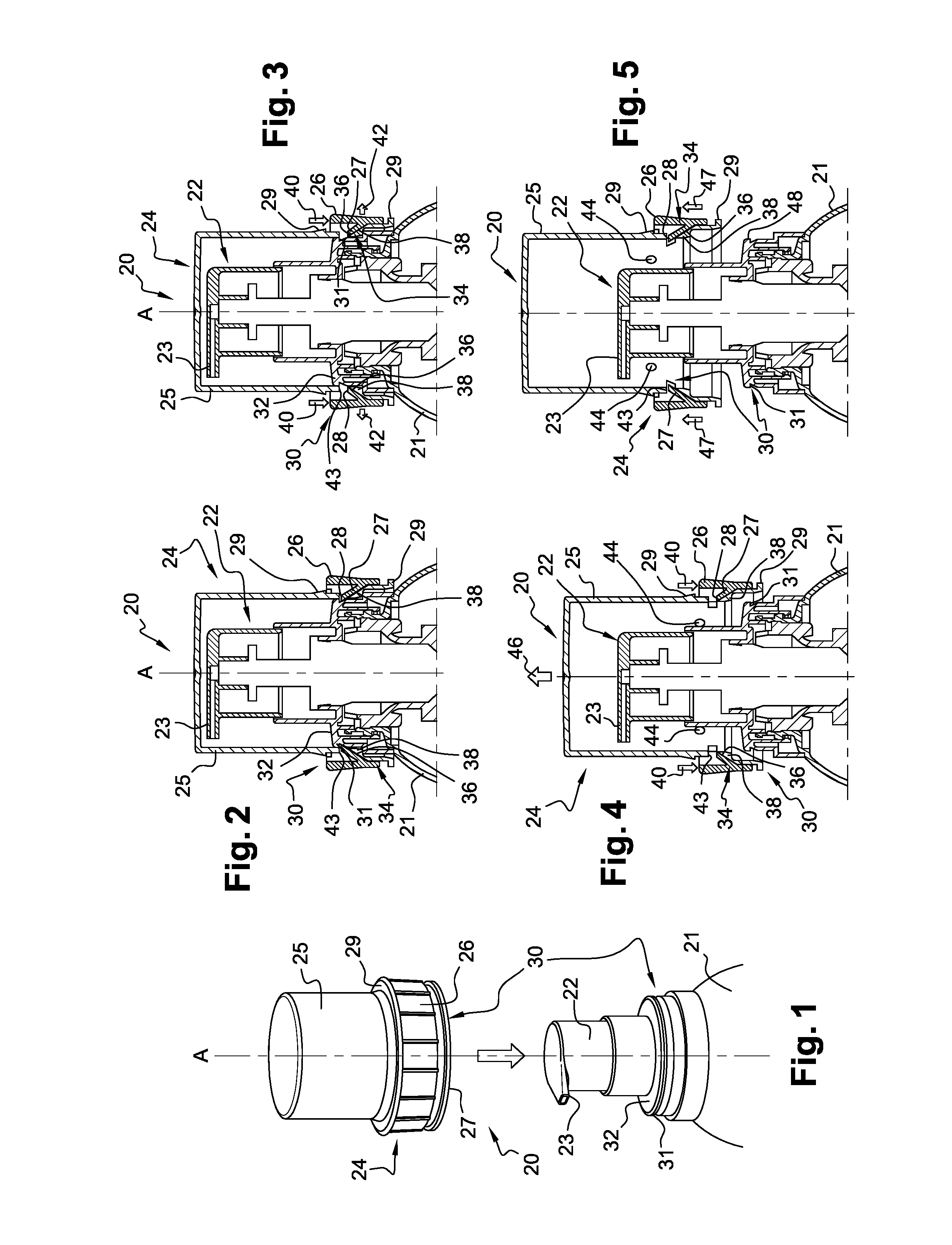
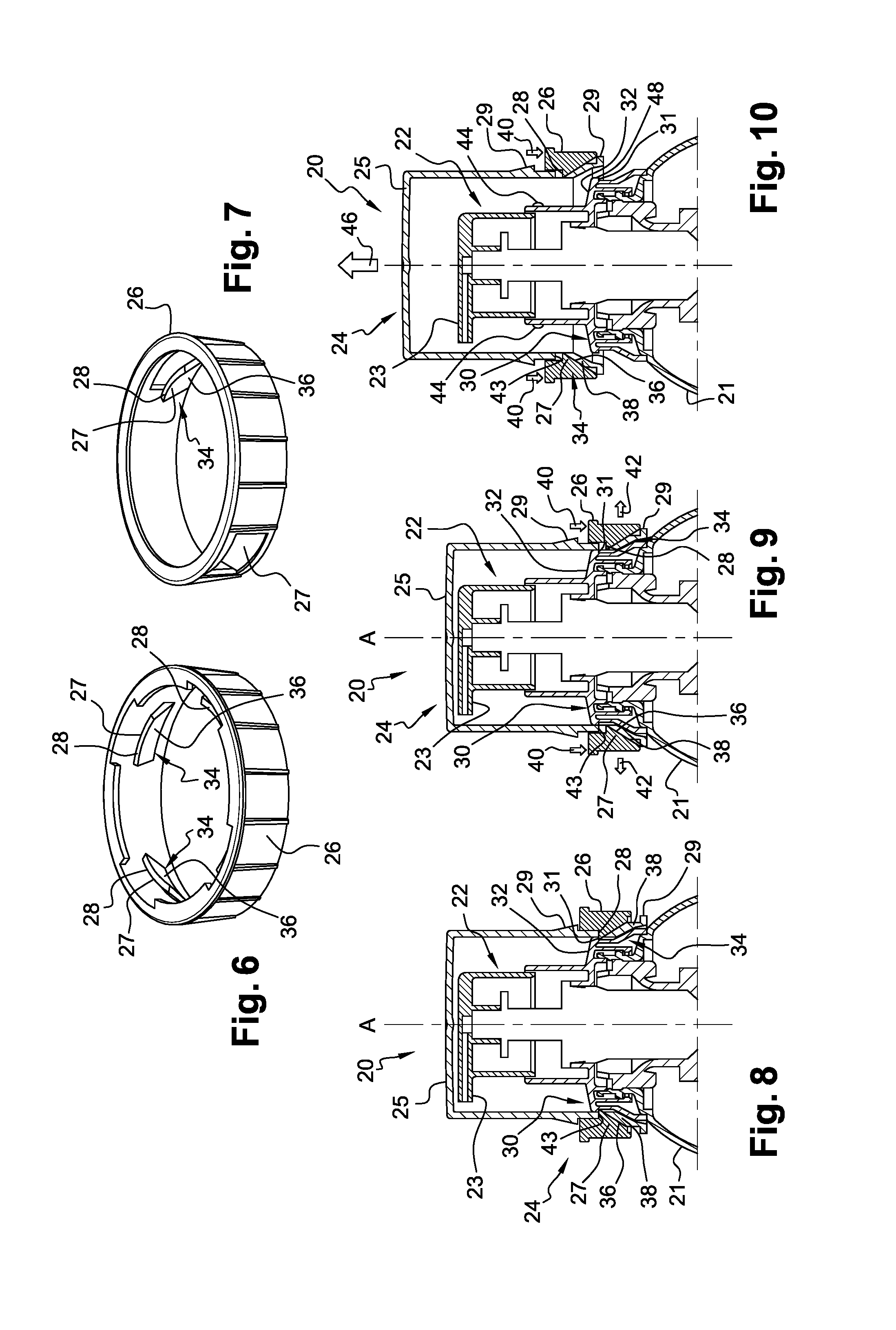
[0106]There is shown in FIGS. 8 to 10 a medical device 20 including a closure device 24 in accordance with the invention. This closure device 24 is mounted on the container 21.

[0107]Differing from the first embodiment, in this case, it is the security ring 26 as a whole (and no longer each lug forming a security element 27) that is elastically deformable in the radial direction and therefore participates in the elastic biasing of the locking abutment 28 of the security element 27 into its cooperation position.

[0108]The principal steps of manipulating the medical device 20 including the closure device 24 in accordance with the second embodiment are deduced, mutatis mutandis, from those of the medical device 20 including the closure device 24 in accordance with the first embodiment: FIG. 8 is analogous to FIG. 3, FIG. 9 is analogous to FIG. 4, and FIG. 10 is analogous to FIG. 5.

third embodiment

[0109]There is represented in FIGS. 11 to 14 a medical device 20 including a closure device 24 in accordance with the invention. This closure device 24 is mounted on the container 21.

[0110]In this case, the dispensing tip 22 is a droplet dispenser operating in a manner known in itself. The dispensing tip 22 is screwed onto a threaded neck 50 of the container 21.

[0111]Moreover, the closure device 24 in accordance with this third embodiment includes an internal cap member 25 including an interior screwthread 52 intended to cooperate with an exterior screwthread 54 carried by the dispensing tip 22 to enable relative screwing movement between the cap assembly 25, 26 and the dispensing tip 22. Alternatively, it could be envisaged that the exterior screwthread 54 be carried directly by the container 21 and enable relative screwing movement between the cap assembly 25, 26 and the container 21.

[0112]The internal cap member 25 including an interior screwthread 52 intended to cooperate with t...


PUM


Abstract

An internal cap member intended to be placed on the container. The internal cap member carries a security ring including a security element including a locking abutment mobile radially between a cooperation position, favored by elastic biasing, in which the locking abutment cooperates with a complementary locking abutment carried by the container, and a separation position, in which the locking abutment is separated from the complementary locking abutment. The security ring is mobile axially on the cap. The closure device also includes an element for transforming the axial movement of the security ring into radial movement of the security element, making it possible for the radial position of the locking abutment to change from its cooperation position to its separation position.

Description

FIELD OF THE INVENTION[0001]The present invention concerns a closure device that is intended to be mounted on the neck of a container also referred to as a reservoir. The container is for example intended to receive a pharmaceutical product in fluid form and may be fitted with a dispensing pump, possibly a metered dispensing pump.BACKGROUND OF THE INVENTION[0002]In known manner, pharmaceutical products are offered for sale in bottles usually comprising a reservoir having a neck on which is mounted a dispensing tip forming a metering pump, for example.[0003]The dispensing tip is conventionally protected by a closure device including a cap intended to be placed on the container or to be removed from that container by relative movement between the cap and the container including an axial component.[0004]Thus it is known to equip the closure device with means for clipping the cap onto the container that can be activated by substantially axial relative movement between the cap and the co...

Claims


Application Information

Patent Timeline
IPC IPC(8): B65D45/30A61J1/14
CPCA61J1/1412B65D45/305A61J1/1418B65D50/046B05B11/0032A61J1/1425B65D2215/04B65D50/06
Inventor PAINCHAUD, GAETANALFONSI, FREDERICDECOCK, THIERRYDUMET, CLEMENT
Owner NEMERA LA VERPILLIERE SAS
Why Eureka
Try Eureka