Expansible Bottle Stopper

a bottle stopper and expandable technology, applied in the field of bottle stoppers, can solve the problems of corks submerged in wine, requiring expensive sealing machines for mass production, and not providing satisfactory sealing effect for long-term preservation

Inactive Publication Date: 2008-05-22
SUNLOT BOTTLE STRPPER
View PDF3 Cites 28 Cited by
  • Summary
  • Abstract
  • Description
  • Claims
  • Application Information

AI Technical Summary

Benefits of technology

[0010]The primary object of the present invention is to provide an expansible bottle stopper including a body, a resilient member, and a movable member that is longitudinally movable relative to the body. By a first-stage longitudinal displacement of the movable member relative to the body, the resilient member is caused to expand radially to tightly attach to an inner wall of a mouth of a container. Long-term preservation of liquid in the container can be attained without the risk of quality degrading.

Problems solved by technology

Metal caps cannot provide a satisfactory sealing effect for long-term preservation and requires expensive sealing machines for mass production.
Corks submerged in wine are liable to break, generating cork scraps in wine.
Furthermore, corks are not suitable for white alcohols and other liquids other than wines.
However, although the peripheral wall of the resilient member can radially expand by downward movement of a shank of the pressing member and the expansible portion of the body, the bottle stopper has too many elements to cut the costs thereof.
Furthermore, the extent of radial expansion of the bottle stopper is limited, which is particularly true for bottles made by blowing glass materials.
Further, bottles made by blowing have small protrusions or recesses in the inner wall of the neck such that precise control of the inner diameter of the neck is impossible while leakage problems arise.
Further, the body of the bottle stopper includes only four petals such that the resilient member has substantially square cross sections when the petals expand radially, failing to provide efficient sealing to the inner wall of the mouth of the bottle.
However, currently available automatic bottle-sealing machines cannot proceed with pivotal movement for moving the lever but perform axial downward movement.
However, currently available automatic bottle-sealing machines can only proceed with axial downward movement.
Further, free rotation of the knob occurs easily, for the bottom of the adjusting rod does not reliably press against the inner wall of the neck of the bottle, failing to achieve the expected sealing effect.
Further, the bottle stopper has no means for retaining it in an appropriate threaded locking state.
The above-mentioned conventional bottle stoppers have various disadvantages and have more elements that lead to high costs.

Method used


Image

  • Expansible Bottle Stopper
  • Expansible Bottle Stopper
  • Expansible Bottle Stopper

Examples


first embodiment

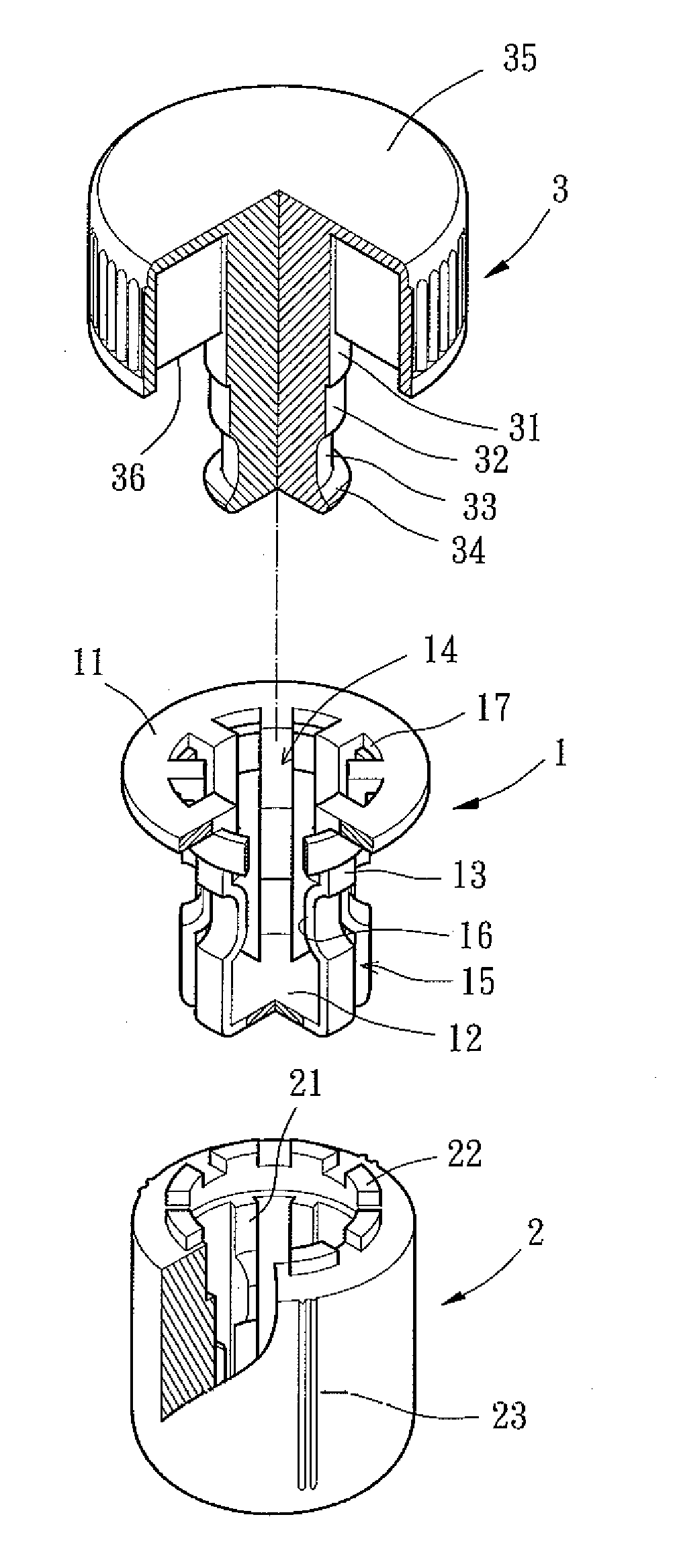
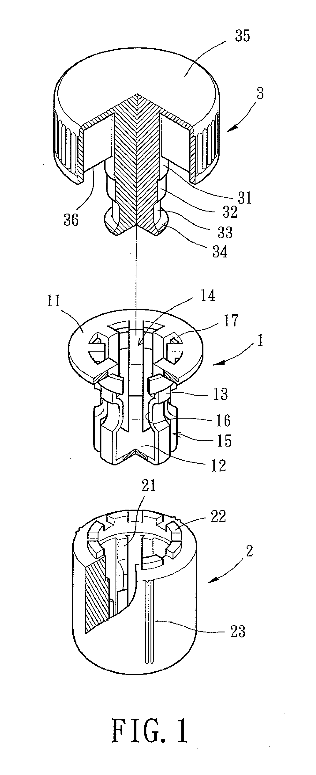
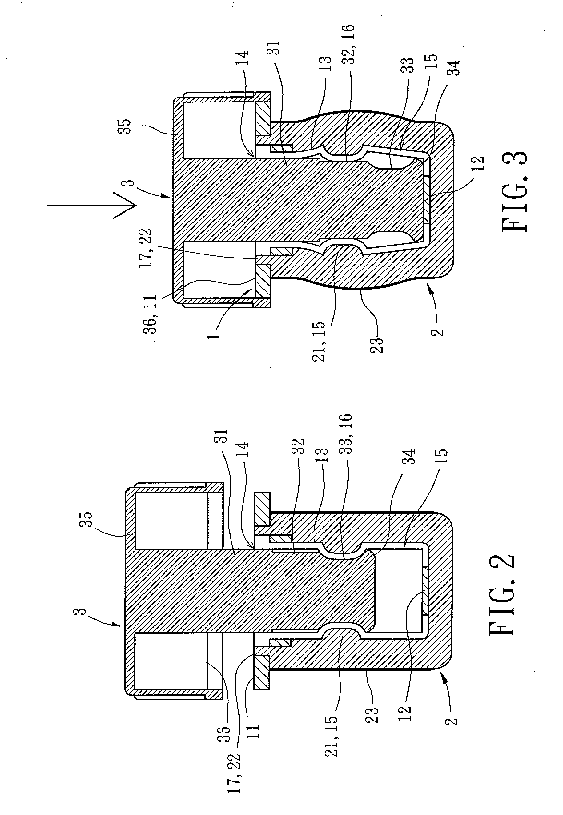
[0023]Referring to FIG. 1, an expansible bottle stopper of a first embodiment according to the present invention includes a body 1, a resilient member 2, and a movable member 3 that can be assembled together to form a bottle stopper or the like for sealing a container such as a glass bottle, potter bottle, china bottle, urn, metal bottle, etc.

[0024]Still referring to FIG. 1, the body 1 may be formed by injection molding of inert material such as plastics. The body 1 includes a top disc 11 having a circular hole 14. A plurality of annularly spaced connecting plates 13 extend from an inner periphery of the circular hole 14. In this embodiment, there are eight connecting plates 13, with a gap 15 formed between a pair of connecting plates 13. Each connecting plate 13 includes an abutting portion 16 extending radially inward toward the circular hole 14. In this embodiment, each abutting portion 16 directly extends inward toward the circular hole 14 from an outer side of one of the connec...

second embodiment

[0030]Referring to FIG. 4, an expansible bottle stopper of a second embodiment according to the present invention includes a body 4, a resilient member 5, and a movable member 6. The body 4 can be formed by injection molding of inert material such as plastics. The body 4 includes an annular wall 41 in the form of a cap. Alternatively, the annular wall 41 can be coupled with a cap made of metal, ceramic, china, wood, or glass materials. The annular wall 41 includes a circular hole 44 therein. A plurality of annularly spaced connecting plates 43 extend from an inner periphery of the circular hole 44, with a gap 45 formed between a pair of adjacent connecting plates 43. Each connecting plate 43 includes an abutting portion 46 extending radially inward toward the circular hole 44. In this embodiment, each abutting portion 46 directly extends inward toward the circular hole 44 from an outer side of one of the connecting plates 43. Distal ends of the connecting plates 43 are connected tog...


PUM


Abstract

An expansible bottle stopper includes a body, a resilient member, and a movable member that is longitudinally movable relative to the body. The resilient member is caused to expand radially by a first-stage longitudinal displacement of the movable member relative to the body or to shrink radially by a second-stage longitudinal displacement of the movable member relative to the body.

Description

BACKGROUND OF THE INVENTION[0001]1. Field of the Invention[0002]The present invention relates to a bottle stopper and, more particularly, to a bottle stopper for a liquid container, which is expansible in a radial direction for sealing the liquid container and shrinkable in the said direction for opening.[0003]2. Description of Related Art[0004]Liquids such as vinegar, oil, whiskey, wine, etc are packaged in containers such as bottles or urns made of glass or potter clay. During packaging, a liquid is injected into the container, and a stopper is inserted into the mouth of the container to seal the container. The outer diameter of the stopper is slightly larger than the inner diameter of the mouth of the container to assure sealing between the inner wall of the mouth of the container and the outer periphery of the stopper mounted in the mouth. Therefore, the stopper is able to resist high pressure inside the container and thereby preserves the liquid in the container.[0005]Tradition...

Claims


Application Information

Patent Timeline
Patent Type & Authority Applications(United States)
IPC IPC(8): B65D39/12
CPCB65D39/12
Inventor LIN, SEN-I
Owner SUNLOT BOTTLE STRPPER
Why Eureka
Try Eureka