

Magnet Sensor Arrangement
- Summary
- Abstract
- Description
- Claims
- Application Information
AI Technical Summary
Problems solved by technology
Method used
Image

Examples
Embodiment Construction
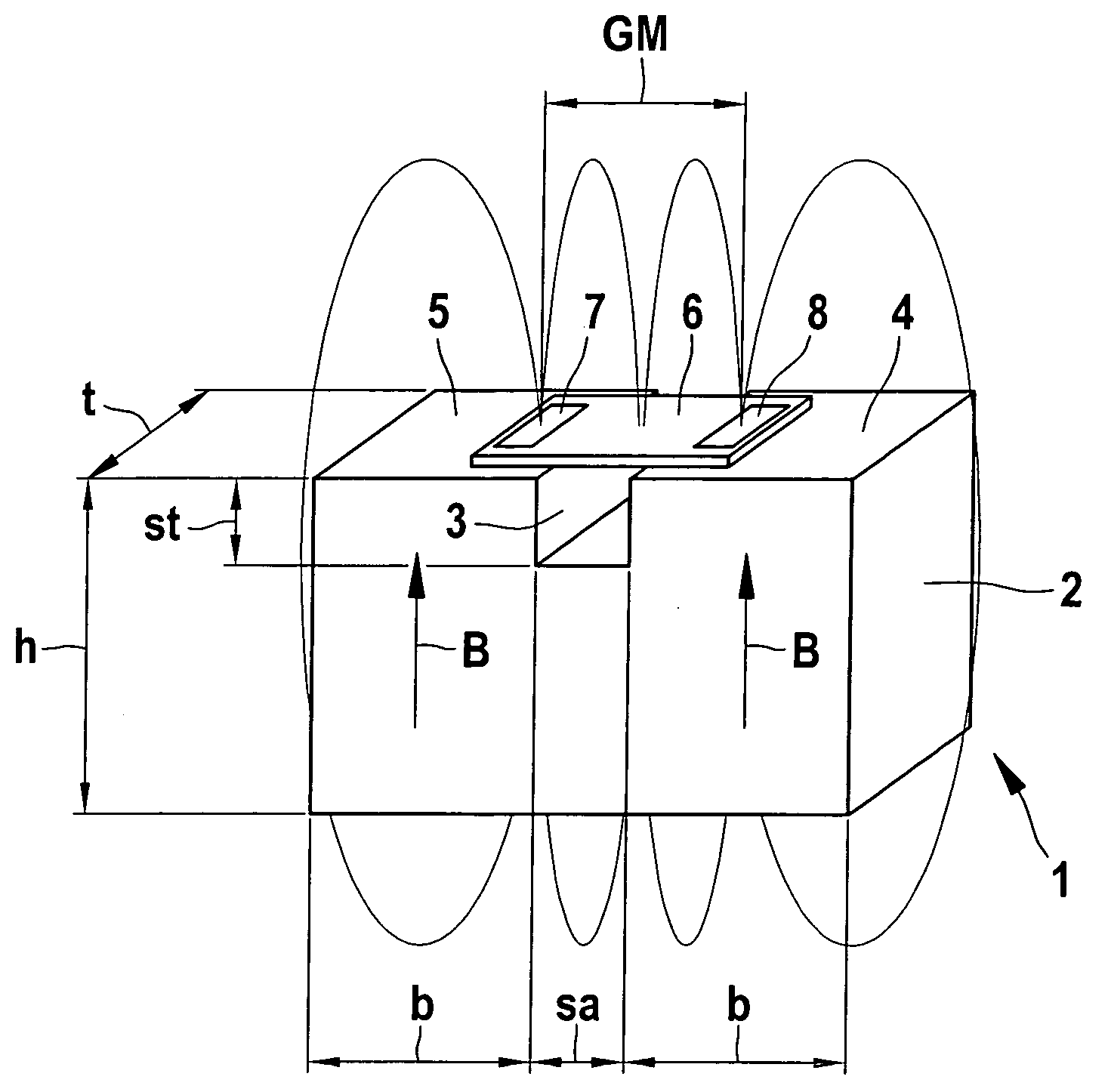
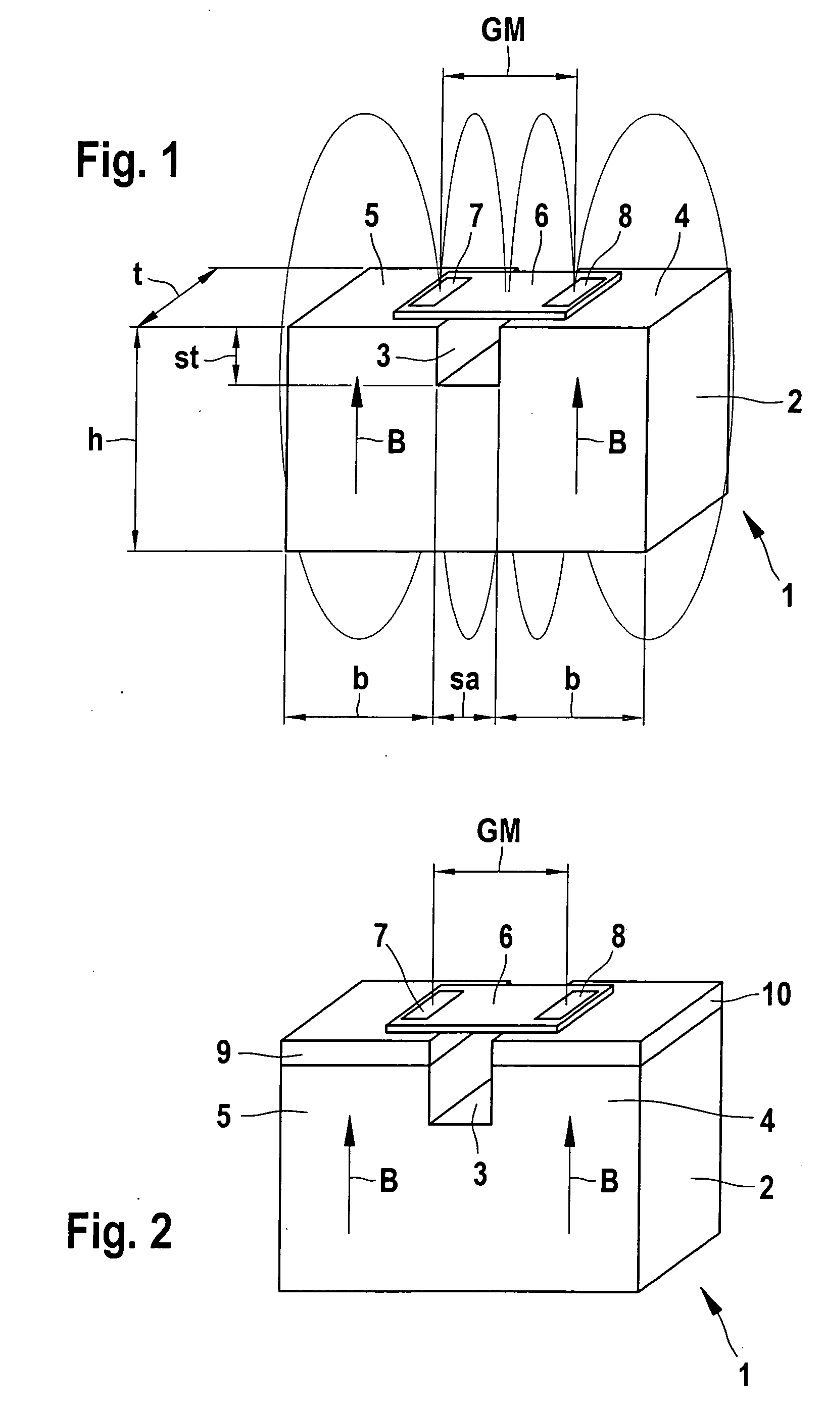
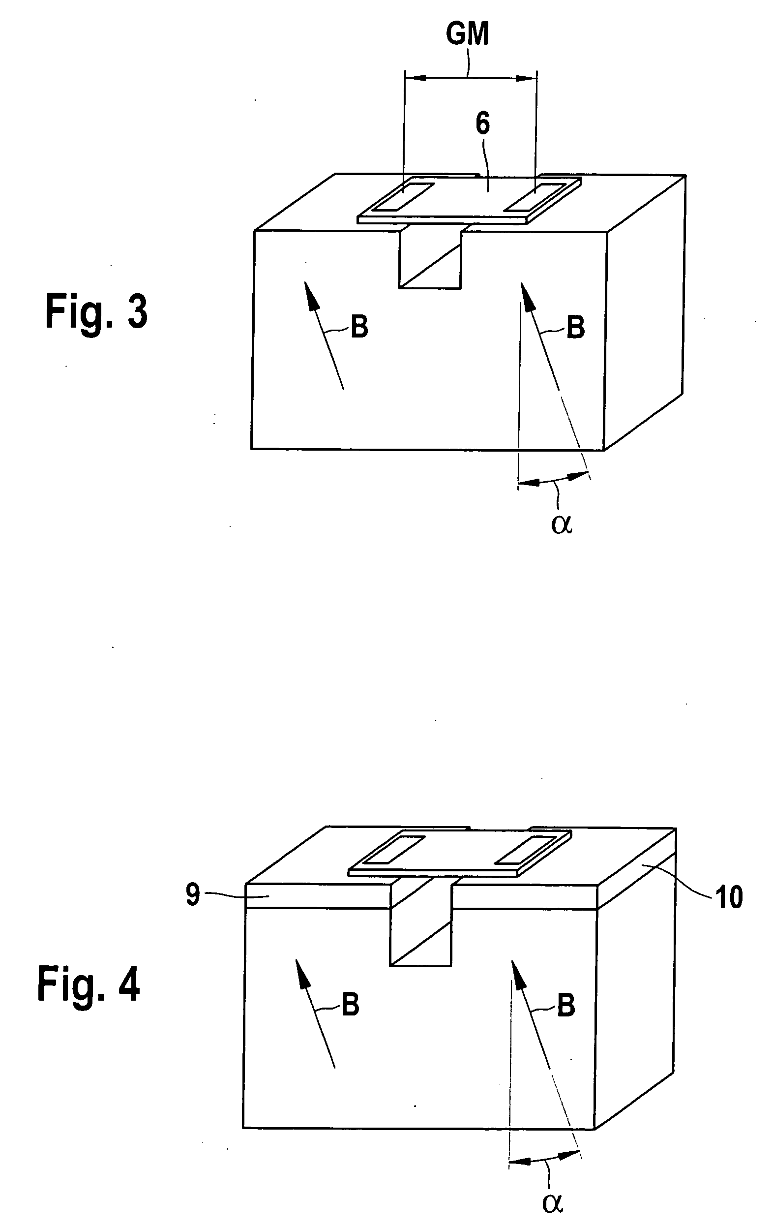
[0031]FIG. 1 is a schematic depiction of a magnetic sensor arrangement 1, which has a permanent magnet embodied in the form of a gap magnet 2. On both sides of a gap 3, this gap magnet 2 has regions 4 and 5 that are magnetized in the same direction, whose respective magnetic field B is aligned with the field lines shown here extending in the direction of a sensor 6. The sensor 6 in this case is embodied in the form of an XMR sensor and has two magnetoresistive sensor elements 7 and 8. The sensor elements 7 and 8 are shown in a gradiometer arrangement—which has the gradiometer distance GM—and detect the changes in the respective field gradients that are caused, for example, by a metallic transmitter element, e.g. a gear depicted in FIG. 5, being moved past the magnetic sensor arrangement 1.
[0032]The optimal operating point of the sensor 6 is set via the distance of the individual magnets 4 and 5, defined by the gap width sa and the gap depth st in relation to each other, and can be a...
PUM
 Abstract
Description
Claims
Application Information