Object tracking system with automated system control and user identification

a technology of object tracking and automated system control, applied in the direction of program control, testing/monitoring control system, instruments, etc., can solve the problems of too large user sophistication and participation, less secure, and less than completely satisfactory in some situations and environments, so as to reduce the level of active participation significantly or completely, the effect of reducing the level of user interaction

Inactive Publication Date: 2008-05-22
KEY CONTROL HLDG
View PDF13 Cites 45 Cited by
  • Summary
  • Abstract
  • Description
  • Claims
  • Application Information

AI Technical Summary

Benefits of technology

[0015]The basic system described briefly above provides for a number of enhanced security features, all of which will be discussed in more detail below. In summary, these features includes the ability to reduce significantly or eliminate completely the level of active participation required from a user during transactions with the system. Rather than being required to enter a user name and PIN number, for instance, a user is automatically identified and verified from his or her biometric data, such as a fingerprint, facial features, or retinal scan. Such means of identification not only reduces user interaction, it also is more secure because it eliminates fraudulent use of the credentials of another to gain illicit access to the system. The locking pin array of the system facilitates intelligent controlled access to tracked objects through a workload / scheduling function. This function allows a supervisor, for example, to designate specific objects to which each user has access and / or to designate times of day (e.g. during each users shift) during which each user is authorized to have access. The system insures that users have access only to objects they should have access to and only at the times when they should have access.
[0016]Other functions facilitated by the system include the ability to force random object rotation among slots of the storage unit by designating to users specific slots to which key tags should be returned upon check in. The key tags are forced to be inserted only in those slots by appropriately manipulating the locking pins of the slots so that only the designated slot is in condition to receive a key tag. Visual confirmation of the condition of keys and their key tags inside the storage unit is made possible by the internal digital camera with wide angle lens and by the clear wall of the unit, which allows for personal visual inspection. Providing two RFID chips on each key tag, one on the key tag and one on a tamper proof tether (the incorporated U.S. Pat. No. 6,262,664 discusses such tamper proof tethers in detail), provides further security against the malicious removal of keys from their key tags and also provides for tracking checked out keys within a specified area to insure that they are not removed from the area. The system also may be coupled to a zonal transition detection system, which may include triangulation receivers, to track the movement of checked out keys or other objects throughout a building, car lot, or other larger area.

Problems solved by technology

While the object tracking system disclosed in the above patents and applications have been very successful, particularly when applied to the tracking of and the control of access to keys in an automotive dealership, they also can be somewhat less than completely satisfactory in some situations and environments.
In some object tracking scenarios, this level of user sophistication and participation is too great, to cumbersome, or otherwise undesirable.
In addition, it is less secure that it might be because a user may divulge his user name and password to another user or to unauthorized personnel, who may then access objects in the system using the falsely acquired credentials.
Prior object tracking systems also include other areas of potential weakness or security lapses.
Prior systems also do not insure that the user returns the same key that was initially checked out by that user.
Since all the keys look similar, it is extremely difficult with such random slot assignment for a user to locate and extract a particular key with the intent, for instance, of stealing a vehicle, without properly logging into the system and thereby creating an audit trail.
However, this security feature can be defeated by a clever user who repeatedly returns the subject key to the same slot within the system so that the physical location of the key is known without logging into the system and requesting the key.

Method used


Image

  • Object tracking system with automated system control and user identification
  • Object tracking system with automated system control and user identification
  • Object tracking system with automated system control and user identification

Examples


Embodiment Construction

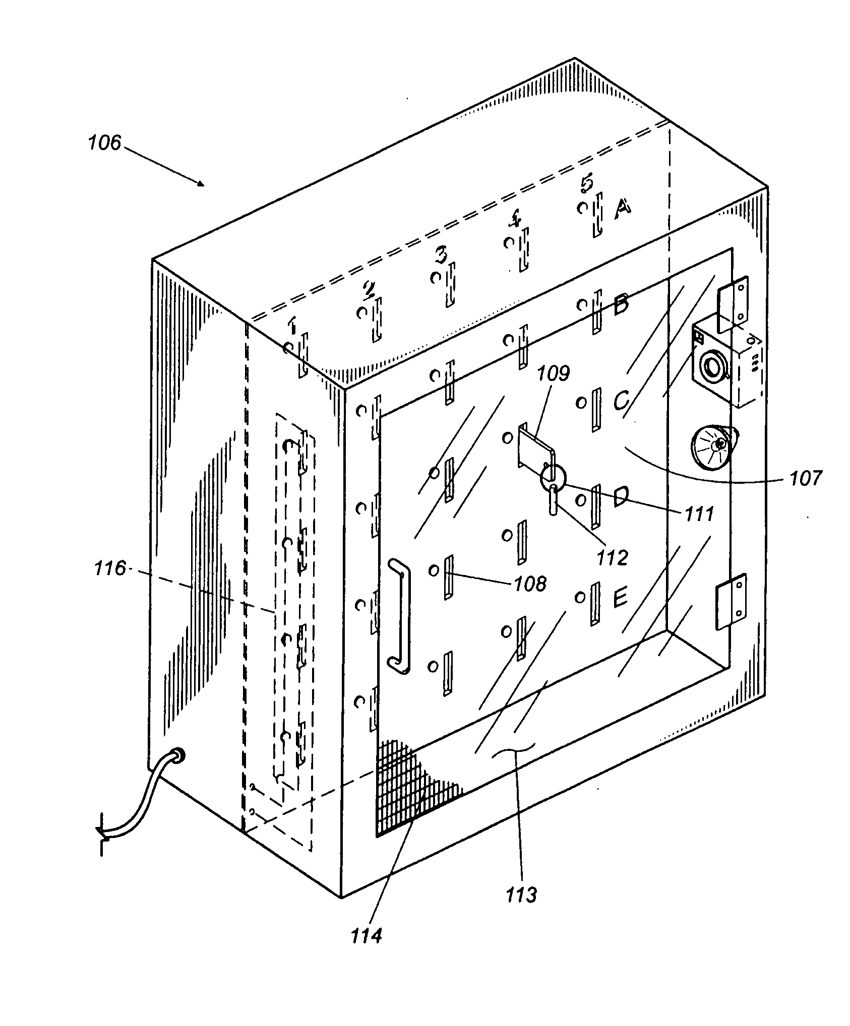
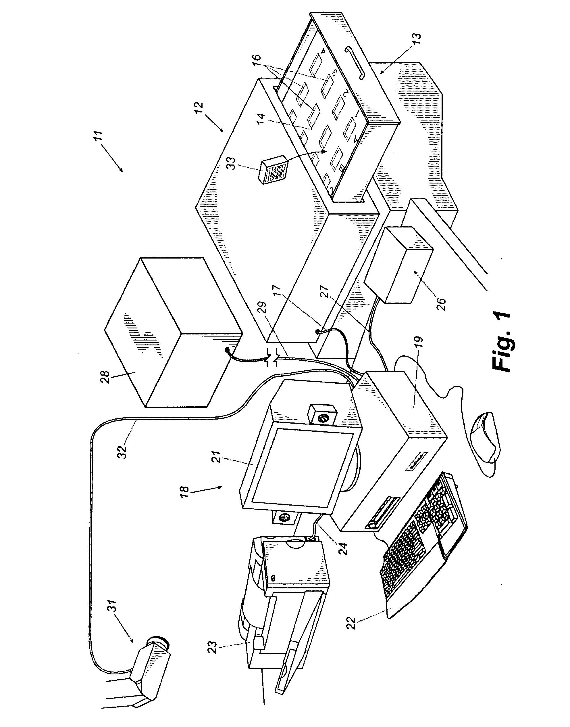
[0035]Referring now in more detail to the drawing figures, wherein like reference numbers indicate, where appropriate, like parts throughout the several views, FIG. 1 illustrates an object tracking and control system 11 that embodies principles of the invention in a preferred form. The system 11 comprises a storage unit 12 that, in this embodiment, takes the form of a cabinet housing an openable drawer 13. The drawer 13 has an internal panel 14 formed with an array of slots or receptacles 13 sized and shaped to receive trackable objects 33, each having at least one unique readable identification code contained within a contact memory button, RFID chip or otherwise. The trackable objects 33 may be key tags attached to keys, object enclosures that contain objects to be tracked, or otherwise, as described in the incorporated patents and patent applications. The storage unit contains a sensor or sensors (not visible) for detecting the identification codes of trackable objects within the...


PUM


Abstract

An enhanced object tracking system for tracking and controlling access to a plurality of objects such as keys is disclosed. The object tracking system implements many improvements including automated user identification using biometric data extracted from the user with a minimum of user interaction, tracking of objects both inside and outside their storage units, the locking of objects within slots of their storage unit to guard against illicit removal and return of keys and to insure random slot rotation, image and visual based inventory verification methodologies, and tracking of objects during times when they are checked out of the system. The result is an intelligent object tracking system with automated control functions and high reliability.

Description

CROSS-REFERENCE TO RELATED APPLICATIONS[0001]This patent application is a continuation of and claims priority to U.S. patent application Ser. No. 10 / 216,334, entitled, “Object Tracking System with Automated System Control and User Identification,” filed Aug. 9, 2002, which claims the benefit of and priority to U.S. provisional patent application Ser. No. 60 / 311,182, filed on Aug. 9, 2001 and U.S. provisional Ser. No. 60 / 333,463, filed on Nov. 27, 2001, all of which are hereby incorporated by reference.TECHNICAL FIELD[0002]This invention relates generally to computer controlled object tracking systems, such as key tracking systems, and more specifically to object tracking systems with built-in intelligent automated controls and security functions and with automated user identification and verification.BACKGROUND[0003]Object tracking systems such as, for example, systems for controlling access to and tracking keys in an automotive dealership, have been available for some time. Among t...

Claims


Application Information

Patent Timeline
Patent Type & Authority Applications(United States)
IPC IPC(8): G08B13/14G05B23/00G06F7/00G06K19/00G08B21/18
CPCG08B13/1427G08B13/2402G08B13/196B25H3/00
Inventor MALONEY, WILLIAM C.
Owner KEY CONTROL HLDG
Why Eureka
Try Eureka