
Projector

Inactive Publication Date: 2008-05-22
FUNAI ELECTRIC CO LTD
View PDF9 Cites 12 Cited by
  • Summary
  • Abstract
  • Description
  • Claims
  • Application Information

AI Technical Summary

Benefits of technology

[0009]The present invention has been proposed in order to solve the aforementioned problems, and an object of the present invention is to provide a projector capabl

Problems solved by technology

In the protrusion display (projector) disclosed in the aforementioned Japanese Patent Laying-Open No. 2005-316177, however, the mesh net is mounted in the case-shaped lamp unit on the prescribed position close to the opening, whereby the operation of arranging the mesh net on the prescribed position in the lamp unit is disadvantageously complicated.
In other words, assembling workability for mounting the mesh net is deteriorated.
Thus, the portions of the heat-resistant organic material cover where the films or nets of the heat-resistant organic material are bonded to each other may disadv

Method used


Image

  • Projector
  • Projector
  • Projector

Examples


Embodiment Construction

[0039]An embodiment of the present invention is now described with reference to the drawings.

[0040]The structure of a projector according to the embodiment of the present invention is described with reference to FIGS. 1 to 8.

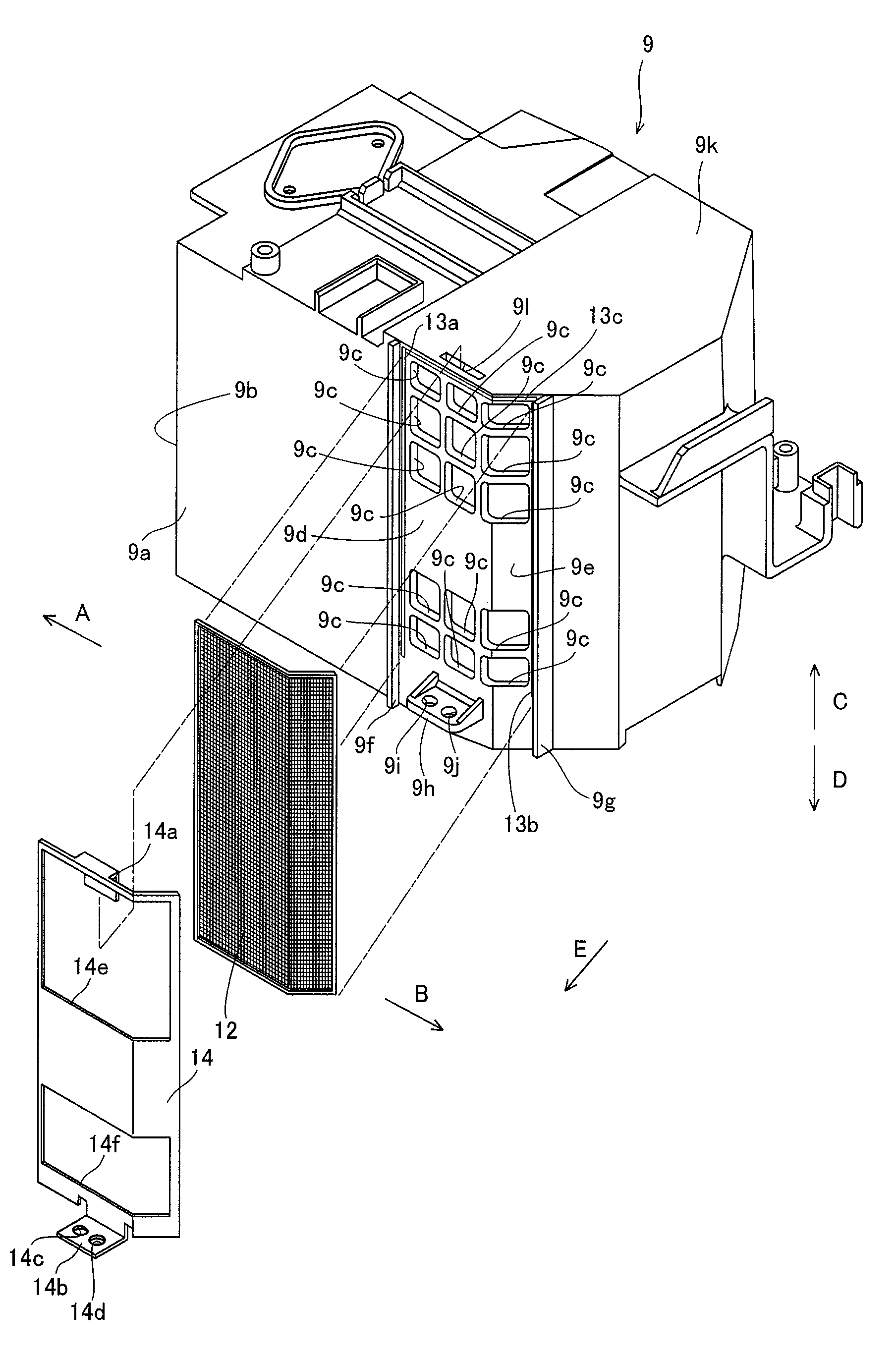
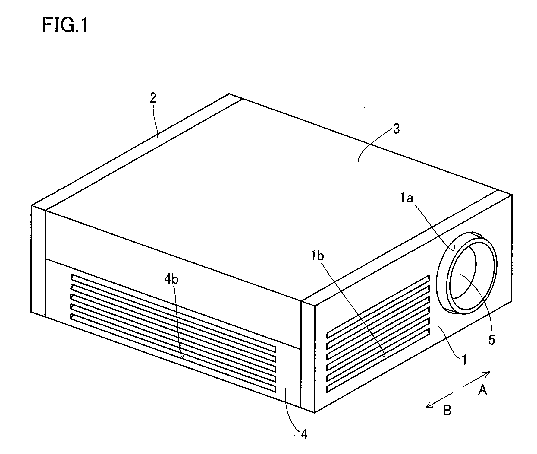
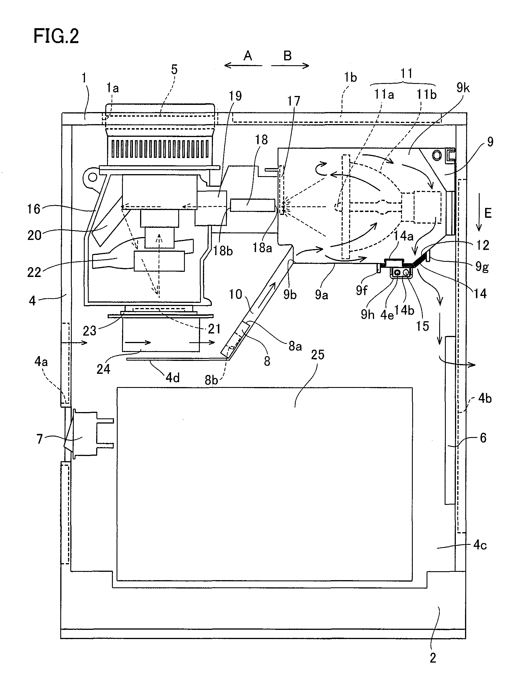
[0041]The projector according to the embodiment of the present invention comprises a front frame 1, a rear frame 2, an upper frame 3 and a lower frame 4, as shown in FIG. 1. The lower frame 4 is an example of the “projector body” in the present invention. A lens receiving portion 1a is provided on a part of the front frame 1 close to a first end (along arrow A), for receiving a projection lens 5 for projecting images. An exhaust port 1b is provided between the center and a second end (along arrow B) of the front frame 1, as shown in FIGS. 1 and 2.

[0042]As shown in FIG. 2, a suction port 4a for introducing air and an outlet 4b for discharging air are formed on a first side surface (along arrow A) and a second side surface (along arrow B) of the lower frame 4 resp...


PUM


Abstract

This projector comprises a source lamp, a lamp storage portion, storing the source lamp therein, including an air discharge opening for discharging internal air from the lamp storage portion and a netlike member so arranged as to cover the outer side of the air discharge opening of the lamp storage portion for inhibiting fragments of the source lamp from being discharged outward from the lamp storage portion through the air discharge opening when the source lamp is broken. The lamp storage portion further includes a protrusion provided on the outer side surface close to the air discharge opening to protrude in a direction intersecting with the extensional direction of the netlike member with a function of inhibiting the fragments of the source lamp from passing through a clearance between the lamp storage portion and the netlike member.

Description

BACKGROUND OF THE INVENTION[0001]1. Field of the Invention[0002]The present invention relates to a projector, and more particularly, it relates to a projector comprising a source lamp and a lamp storage portion.[0003]2. Description of the Background Art[0004]A projector comprising a source lamp and a lamp storage portion is known in general, as disclosed in Japanese Patent Laying-Open Nos. 2005-316177 and 2003-7128, for example.[0005]The aforementioned Japanese Patent Laying-Open No. 2005-316177 discloses a protrusion display (projector) comprising a source lamp, a case-shaped lamp unit (lamp storage portion), storing the source lamp, having an opening serving as an air outlet and a mesh net arranged on the opening of the lamp unit. The mesh net is mounted in the case-shaped lamp unit on a prescribed position close to the opening.[0006]The aforementioned Japanese Patent Laying-Open No. 2003-7128 discloses a light source unit, employed for a liquid crystal projector, comprising a hea...

Claims


Application Information

Patent Timeline
IPC IPC(8): G03B21/20
CPCG03B21/16G03B21/2086G03B21/145
Inventor HAMADA, SHINGO
Owner FUNAI ELECTRIC CO LTD
Learn More