Optical Fiber Module

a technology of optical fiber and fiber module, applied in the field of optical fiber modules, can solve the problems of connection loss and connection loss at the location of connection, and achieve the effect of not increasing the loss of connection

Inactive Publication Date: 2008-05-22
SUMITOMO ELECTRIC IND LTD
View PDF20 Cites 82 Cited by
  • Summary
  • Abstract
  • Description
  • Claims
  • Application Information

AI Technical Summary

Benefits of technology

[0009]According to the optical fiber module of the present invention, the pigtail fiber connected to the functional optical fiber extends out of the receptacle and connects directly to external optical equipment. Therefore, connection loss does not increase. In addition,

Problems solved by technology

However, connection loss occurs at the location of the connection.
For this reason, an obstruction will result if a pigtail fiber 4 is too long to be connected t

Method used


Image

  • Optical Fiber Module
  • Optical Fiber Module
  • Optical Fiber Module

Examples


Embodiment Construction

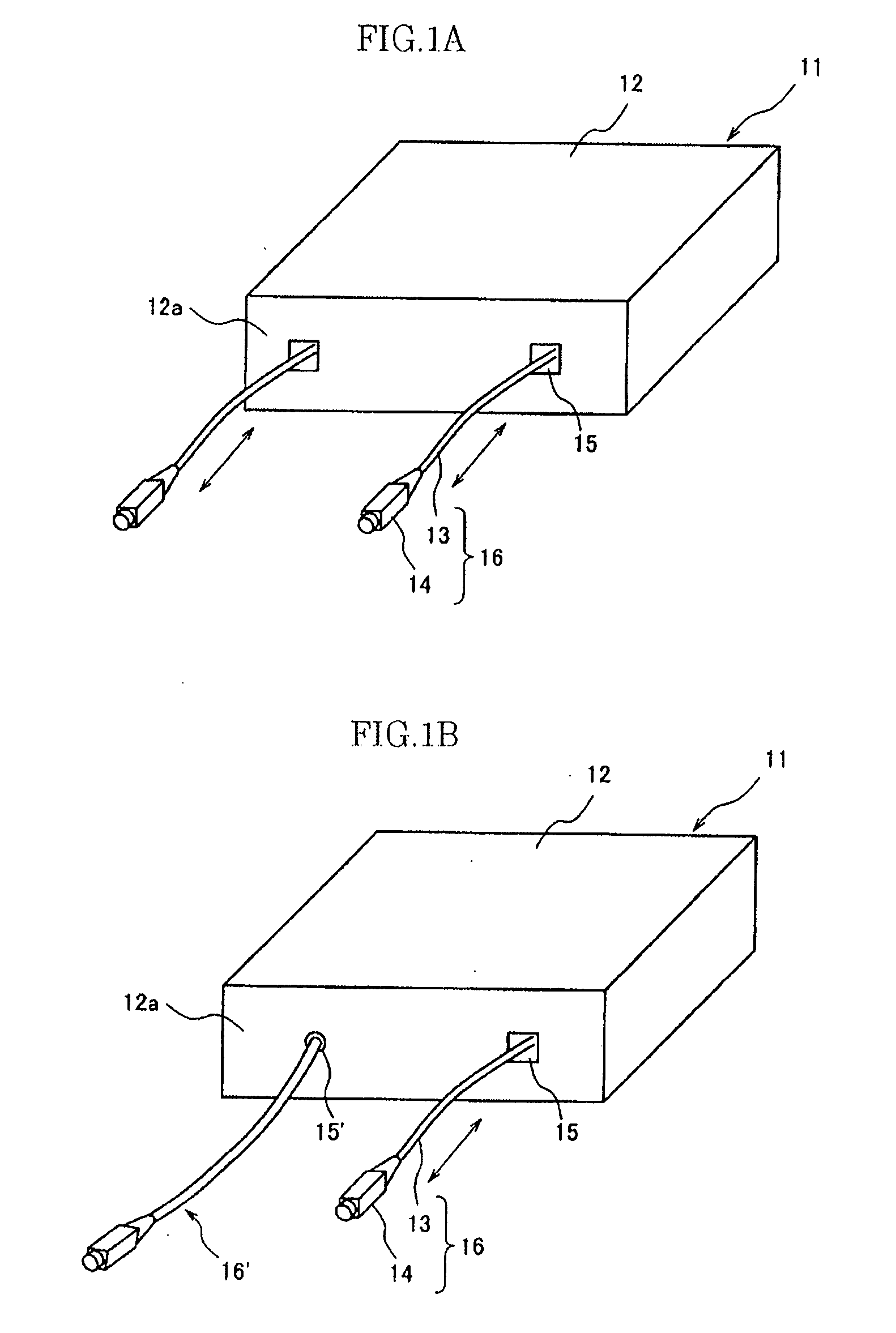
[0043]An embodiment of the present invention will be described below with reference to the drawings. The drawings are used for descriptive purposes and do not limit the scope of the invention. In the drawings, the same symbols mark the same parts in order to avoid repeated descriptions. The ratios of dimensions in the drawings are not necessarily accurate.

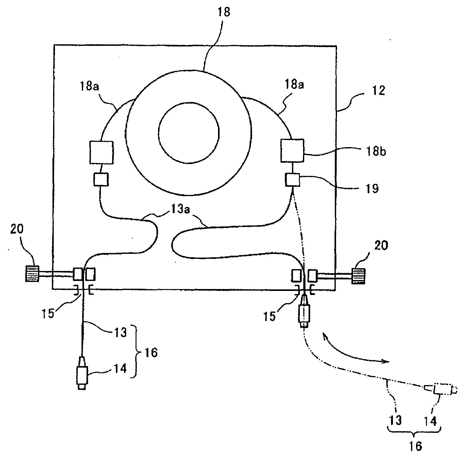
[0044]FIGS. 1A and 1B are perspective views of an embodiment of an optical fiber module according to the present invention. An optical fiber module 11 includes a pigtail fiber 13 which is guided to a receptacle 12 and connected with a functional optical fiber in the receptacle 12, similar to the optical fiber module 7 and the outer end of the pigtail fiber connects to an optical connector 14. The functional optical fiber, which has been wounded in a coiled shape, may be a dispersion compensating fiber (DCF), which has a chromatic dispersion of opposite sign to that of a transmission line and which compensates a chromatic dispersion...


PUM


Abstract

An optical module is connected to external optical equipment with low loss, and excess length portion of a pigtail fiber does not cause an obstruction. The optical fiber module includes (1) a functional optical fiber; (2) a receptacle configured and arranged to accommodate the functional optical fiber; (3) a pigtail fiber that is connected to the functional optical fiber, and disposed so as to be extendable or retractable from the receptacle; and (4) a connecting terminal that is connected to the pigtail fiber, and to which external equipment is connected.

Description

TECHNICAL FIELD[0001]The present invention relates to an optical fiber module that accommodates a functional optical fiber or the like, and comprises an optical connecting terminal for external optical equipment.BACKGROUND ART[0002]An optical fiber module such as a dispersion compensating fiber module includes, for example, an optical fiber wounded into a coil shape and accommodated in a box-shaped receptacle and an input / output optical connecting terminal provided on a panel of the receptacle (for example, see Japanese Patent Application Laid-Open No. 2003-4951). A functional optical fiber such as a dispersion compensating fiber is usually wound on a bobbin or is placed in a receptacle in a manner in which it has been molded with resin. The input / output ends of the functional optical fiber are connected and anchored via excess length portions to optical connectors, connecting adapters, or the like provided on a front panel.[0003]FIGS. 8A and 8B are perspective views showing an opti...

Claims


Application Information

Patent Timeline
IPC IPC(8): G02B6/00G02B6/42
CPCG02B6/4457G02B6/4452
Inventor YAMAMOTO, YOSHINORIMIYAMOTO, TOSHIYUKI
Owner SUMITOMO ELECTRIC IND LTD
Why Eureka
Try Eureka