Metering pump for dispensing liquid

Active Publication Date: 2008-05-22
SOC DES PROD NESTLE SA
View PDF15 Cites 39 Cited by
  • Summary
  • Abstract
  • Description
  • Claims
  • Application Information

AI Technical Summary

Benefits of technology

[0030]In another embodiment of the invention, the invention is incorporated into a support for mounting a collapsible container bag containing a liquid and a metering pump within a cabinet. The collapsible container bag has a flexible tube for discharging the liquid. The cabinet has a cabinet aperture located in a bottom wall of the cabinet. The support comprises a base plate having a base plate aperture with a base plate magnetic material located in proximity thereto. The base plate is secured to the bottom wall of the cabinet with the base plate aperture being aligned with the cabinet aperture. A base plate aligner is defined by the base plate. A saddle comprising plural supports has a saddle aperture located between the plural supports. The saddle has a saddle aligner for cooperating with the base plate aligner for aligning the saddle aperture with the base plate aperture. A magnet is located on the saddle in proximity to the saddle aperture magnetically coupling with the base plate magnetic material for maintaining the position of the saddle relative to the base plate. A collapsible container bag contains a liquid. A flexible tube extends from the collapsible container bag for discharging the liquid from the collapsible container bag. The flexible tube is insertable through the saddle aperture and the base plate aperture to extend from the cabinet aperture with the plural supports of the saddle supporting the collapsible container bag. A flexible tube magnetic material is magnetically coupled with the magnet located on the saddle for maintaining the position of the flexible tube and the collapsible container bag relative to the saddle.
[0031]In still another embodiment of the invention, the invention is incorporated into a pump drive for driving a metering pump including a flexible tube having a pressure relief valve connected to a source of a liquid. The pump drive comprises an electric motor has a rotary drive defining a rotary drive axis. A drive roller is secured to the rotary drive and located offset from the rotary drive axis. A yoke has a generally rectangular yoke apert

Problems solved by technology

However, it is more difficult to accurately discharge a metered amount of li

Method used


Image

  • Metering pump for dispensing liquid
  • Metering pump for dispensing liquid
  • Metering pump for dispensing liquid

Examples


second embodiment

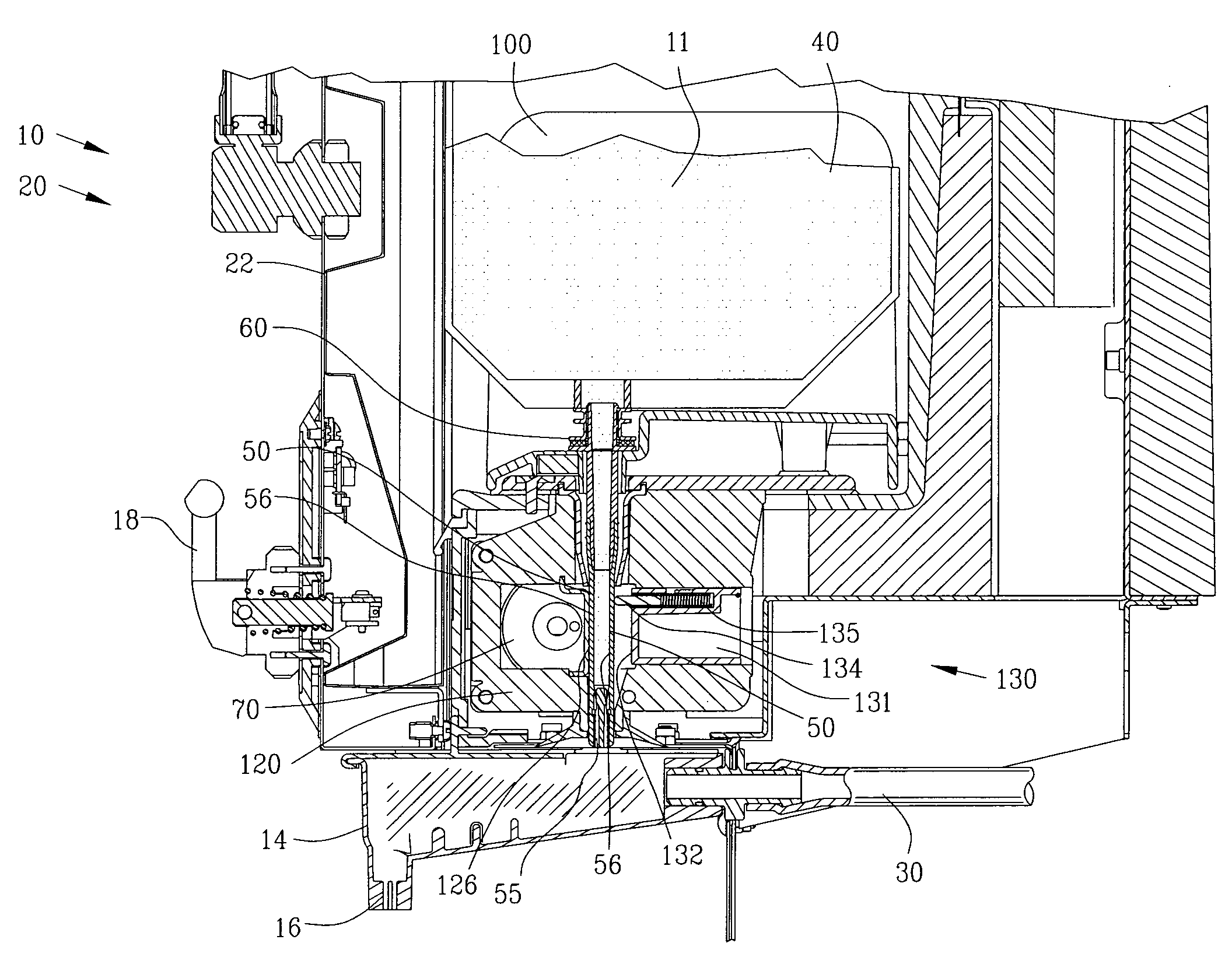
[0112]FIGS. 17-19 illustrate a sequence of pumping utilizing the motor drive unit 50A. In this example, the pump drive 80 and the reciprocating member 130 has been altered to push the reciprocating member 130 into engagement with the metering pump flexible tube 56. In contrast, the pump drive 80 and the reciprocating member 130 shown in FIGS. 10-16 pulls the reciprocating member 130 into engagement with the metering pump flexible tube 56.

[0113]FIG. 17 illustrates the reciprocating member 130 in the retracted position.

[0114]FIG. 18 is a view similar to FIG. 17 with a sealing element 134 pinching the metering pump flexible tube 56 against the compression surface 126.

[0115]FIG. 19 is a view similar to FIG. 18 with a pumping element 133 collapsing the metering pump flexible tube 56 against the compression surface 126 for pumping the liquid concentrate 11 from a pressure relief valve 55.

[0116]FIGS. 20-22 are magnified views of FIGS. 17-19 illustrating the sequence of pumping of the meter...

third embodiment

[0124]FIGS. 26-28 illustrate a pressure relief valve 55E. The pressure relief valve 55E includes a valve element 162E, a deformable biasing element 164E and a valve seat 166E. The deformable biasing element 164E urges the valve element 162E into engagement with the valve seat 166E for closing the pressure relief valve 55E.

[0125]An insert 170E extends between a first and a second end 171E and 172E. The insert 170E includes an insert input orifice 173E and an insert output orifice 174E interconnected by an insert passageway 176E. An insert projection 178E extends radially outwardly from the insert 170E. Preferably, the insert 170E is molded from a rigid polymeric material for insertion within the internal duct 53E of the flexible metering pump tube 56E. Upon insertion of the insert 170 within the internal duct 53E of the flexible metering pump tube 56E, the insert projection 178E engages with a flexible tube recess 58E within the flexible metering pump tube 56E to maintain the positio...


PUM


Abstract

A pump for metering a liquid is disclosed comprising a flexible tube connected to a container with a pressure relief valve located in the flexible tube. A housing defines an aperture for receiving the flexible tube with a compression surface located adjacent to the aperture. A reciprocating member has a sealing element and a pumping element. A drive moves the sealing element for pinching the flexible tube against the compression surface upstream from the pressure relief valve for trapping liquid between the sealing element and the pressure relief valve. The drive moves the pumping element for collapsing the flexible tube against the compression surface for pumping the trapped liquid to discharge a metered quantity of the liquid from the pressure relief valve.

Description

BACKGROUND OF THE INVENTION[0001]1. Field of the Invention[0002]This invention relates to the pumping of liquids and more particularly to an improved pump for metering a liquid from a container.[0003]2. Description of the Related Art[0004]Metering pumps have been well known in the art for pumping and / or dispensing a specific volume of liquid from a container. There are two basic types of metering pumps namely a single action metering pump and a multiple action metering pump. In a single action metering pump, the liquid is pumped and dispensed in a single action or single stroke of the metering pump. Typically, a volume is filled with a metered volume of liquid from a larger container and then the metered volume of liquid is pumped or discharged from the metered volume for end use.[0005]In a multiple action metering pump, a volume is filled with their metered volume of liquid from a larger container and then the body of liquid is pumped or discharged from the metered volume. Thereaft...

Claims


Application Information

Patent Timeline
IPC IPC(8): F04B43/09F04B43/08F16M13/02
CPCB67D1/108B67D1/1231F04B43/09B67D2001/0827F04B43/08B67D1/1279Y10T137/469
Inventor BARON, RICHARD D.GARBEE, STEVEN A.QUADROS, VALDEMIRO M.HACKEY, ALAN LEE
Owner SOC DES PROD NESTLE SA
Why Eureka
Try Eureka