Bone repair device and method

a bone repair and bone technology, applied in the field of bone repair devices and methods, can solve the problems of reducing nerve function, extreme and debilitating pain, and temporarily unsecured and unrestrained rods of patients who suffer from such conditions

Active Publication Date: 2008-05-22
AESCULAP IMPLANTS SYST LLC
View PDF19 Cites 54 Cited by
  • Summary
  • Abstract
  • Description
  • Claims
  • Application Information

AI Technical Summary

Problems solved by technology

Patients that suffer from such conditions usually experience extreme and debilitating pain, as well as diminished nerve function.
This has the disadvantage of leaving the rod temporarily unsecured and unrestrained, potentially allowing the rod and vertebra to shift out of the set position.
Therefore, known jig assemblies have certain characteristics that may be undesirable for spinal reduction procedures.

Method used


Image

  • Bone repair device and method
  • Bone repair device and method
  • Bone repair device and method

Examples


first embodiment

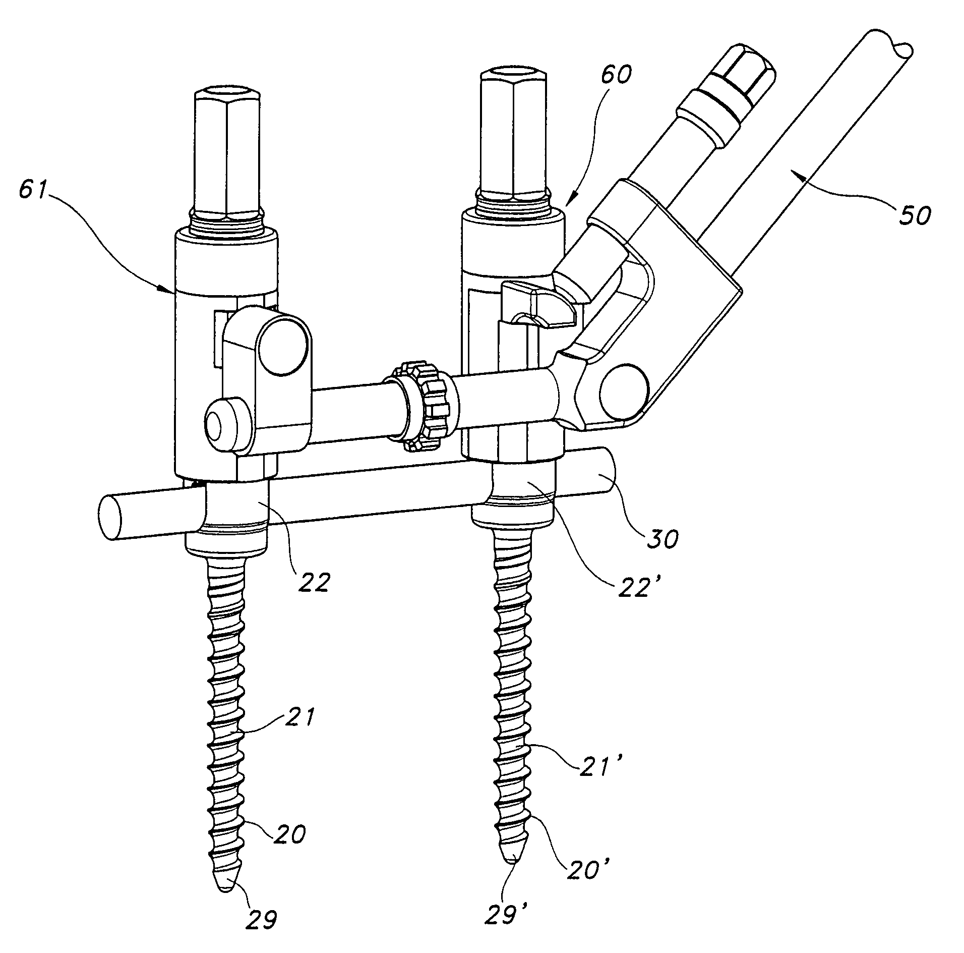
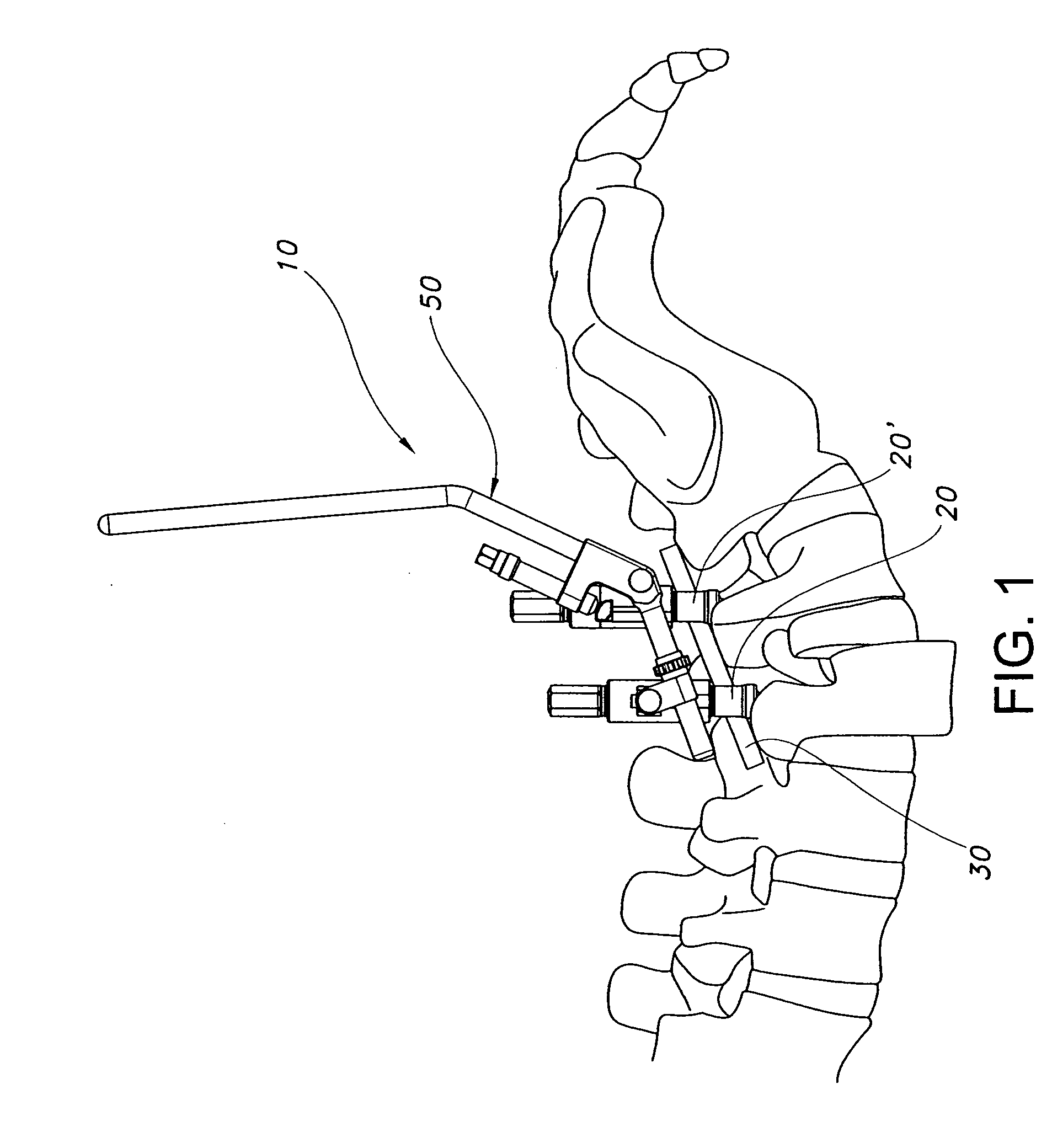
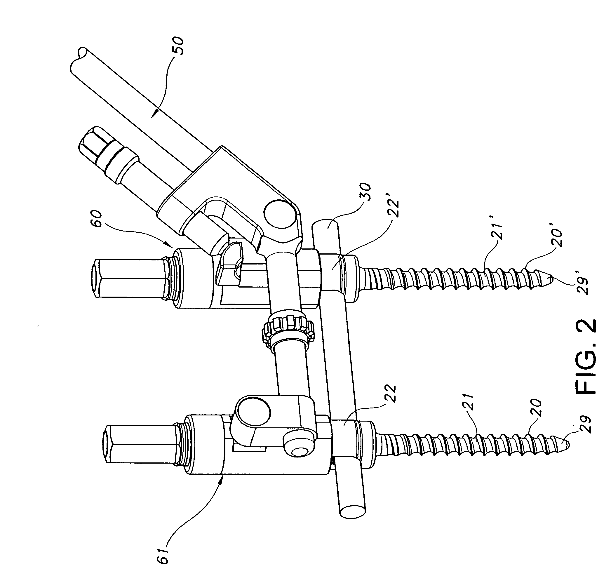
[0026]Referring now to the drawing figures generally, and FIGS. 1 and 2 in particular, a spondylolisthesis reduction assembly 10 in accordance with the present invention is shown. It should be understood that multiple assemblies having configurations as shown in FIG. 1, or other configurations, may be used in a given procedure. The arrangements illustrated herein are intended only for purposes of illustrating possible configurations. Assembly 10 includes two bone fixation screws 20 and 20′ and an adjustment apparatus or jig 50. Bone screw 20 is screwed into a vertebral body 4 to be repositioned, and bone screw 20′ is screwed into an adjacent vertebral body 6. Screws 20 and 20′ collectively anchor and support an elongated fixation member, which is shown as a cylindrical rod 30. Rod 30 exerts forces on the vertebra to alter the shape of the spine. It will be understood that in surgical procedures, the rod may span three or more vertebra. For purposes of clarity, however, rod 30 is sho...

third embodiment

[0062]Referring now to FIGS. 11-15, an engagement assembly 260 in accordance with the invention is shown. Engagement assembly 260 includes a one-piece outer sleeve 270 and a locking sleeve 280. Engagement assembly 260 permits locking sleeve 280 and a set screw 240 to be driven into a screw cap simultaneously with a single torque-applying instrument. Because the engagement assembly 260 has a one-piece outer sleeve, the assembly has fewer components to assemble during the manufacturing process.

[0063]Outer sleeve 270 includes a hex head portion 275 and a cylindrical wall 276 that is integrally connected with the hex head portion. Hex head 275 and wall 276 are hollow and form a bore 277 that extends along the longitudinal axis of the outer sleeve 270. Hex head 275 includes a tool-receiving opening 274 adapted to receive a torque-applying tool, and cylindrical wall 276 has a socket end 272 configured to fit over a pedicle screw cap 222, similar to the other embodiments described herein.

[...


PUM


Abstract

An assembly for treating a spinal disorder includes a sleeve having a socket end, a tool-receiving end and a wall extending between the socket end and tool-receiving end. The socket end has a socket opening for receiving a bone fixation screw cap and a pair of opposing notches for accommodating an elongated fixation member. A sleeve wall forms a hollow bore extending axially between the tool-receiving end and the socket end of the sleeve. A method for repairing a spinal disorder includes the step of inserting a polyaxial screw into a vertebral bone, where the polyaxial screw has a screw cap. An elongated fixation member is inserted into the screw cap, followed by a fastener which is inserted into the screw cap in proximity to the elongated fixation member. An adjustment device is connected to the screw cap to adjust the position of the polyaxial screw and vertebral bone.

Description

FIELD OF THE INVENTION[0001]The present invention relates generally to devices for treating spinal disorders, and particularly to an apparatus and method for securing a spine rod to a patient's spine.BACKGROUND OF THE INVENTION[0002]The spinal column is a highly complex system of bones and connective tissues that provides support for the body and protects the delicate spinal cord and nerves. The spinal column includes a series of vertebrae stacked one atop the other, each vertebral body including an inner or central portion of relatively weak cancellous bone and an outer portion of relatively strong cortical bone. Situated between each vertebral body is an intervertebral disc that cushions and dampens compressive forces experienced by the spinal column. A vertebral canal containing the spinal cord and nerves is located behind the vertebral bodies.[0003]There are many types of spinal column disorders including scoliosis (abnormal lateral curvature of the spine), kyphosis (abnormal fo...

Claims


Application Information

Patent Timeline
Patent Type & Authority Applications(United States)
IPC IPC(8): A61B17/58A61B17/56
CPCA61B17/7032A61B17/7037A61B2019/307A61B17/7091A61B17/708A61B2090/037
Inventor DALTON, BRIAN E.WING, CHARLIENAWARYNSKI, JOHN
Owner AESCULAP IMPLANTS SYST LLC
Why Eureka
Try Eureka