Systems and Arrangements for Cache Management

a cache and memory technology, applied in the field of processors, can solve the problems of processor idle time, large number of clock cycles, and relatively slow data transfer between the processor and external memory, so as to reduce the frequency of cache reloads, improve overall system performance, and reduce cache miss rate

Inactive Publication Date: 2008-05-22
IBM CORP
View PDF13 Cites 102 Cited by
  • Summary
  • Abstract
  • Description
  • Claims
  • Application Information

AI Technical Summary

Benefits of technology

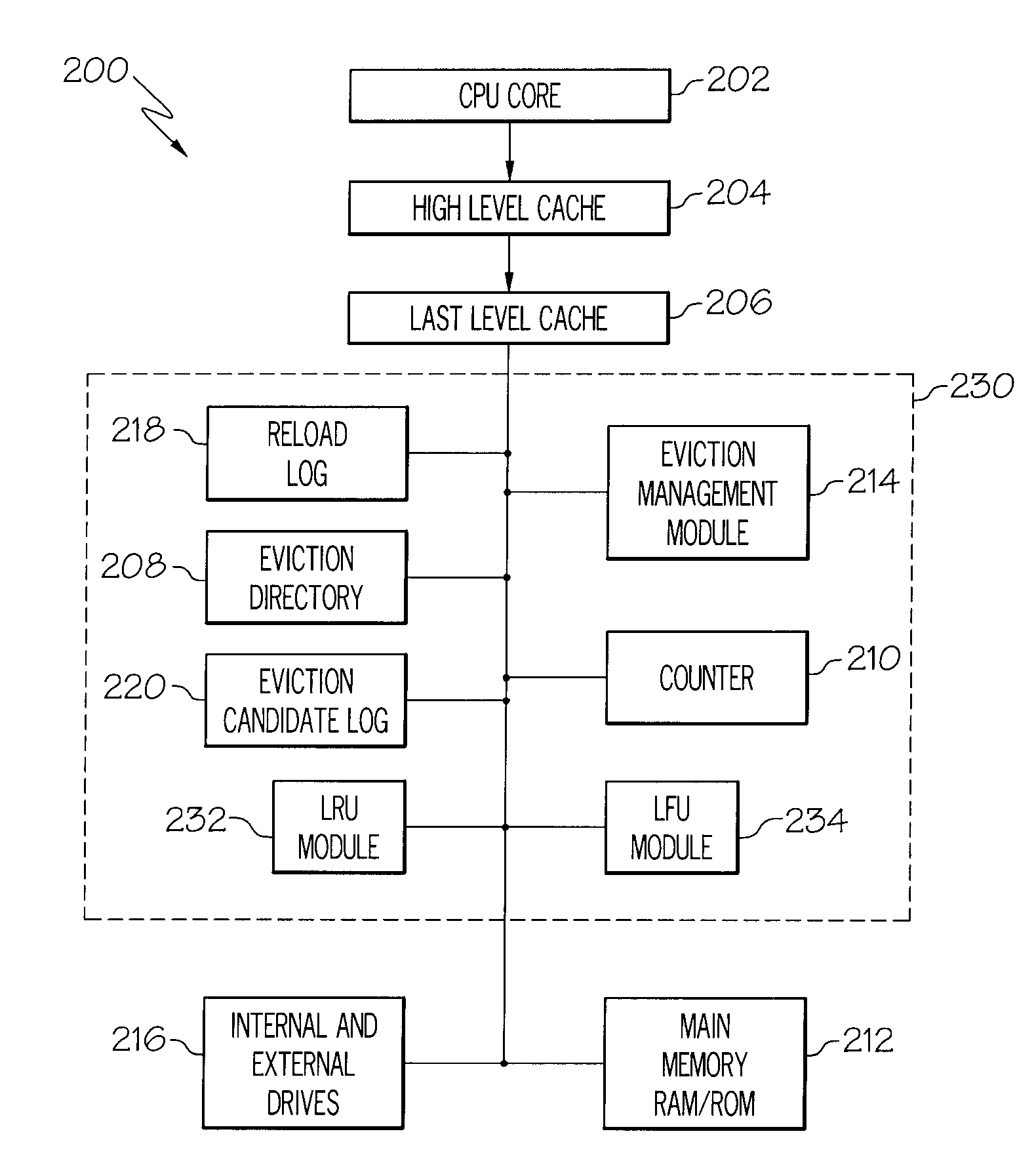
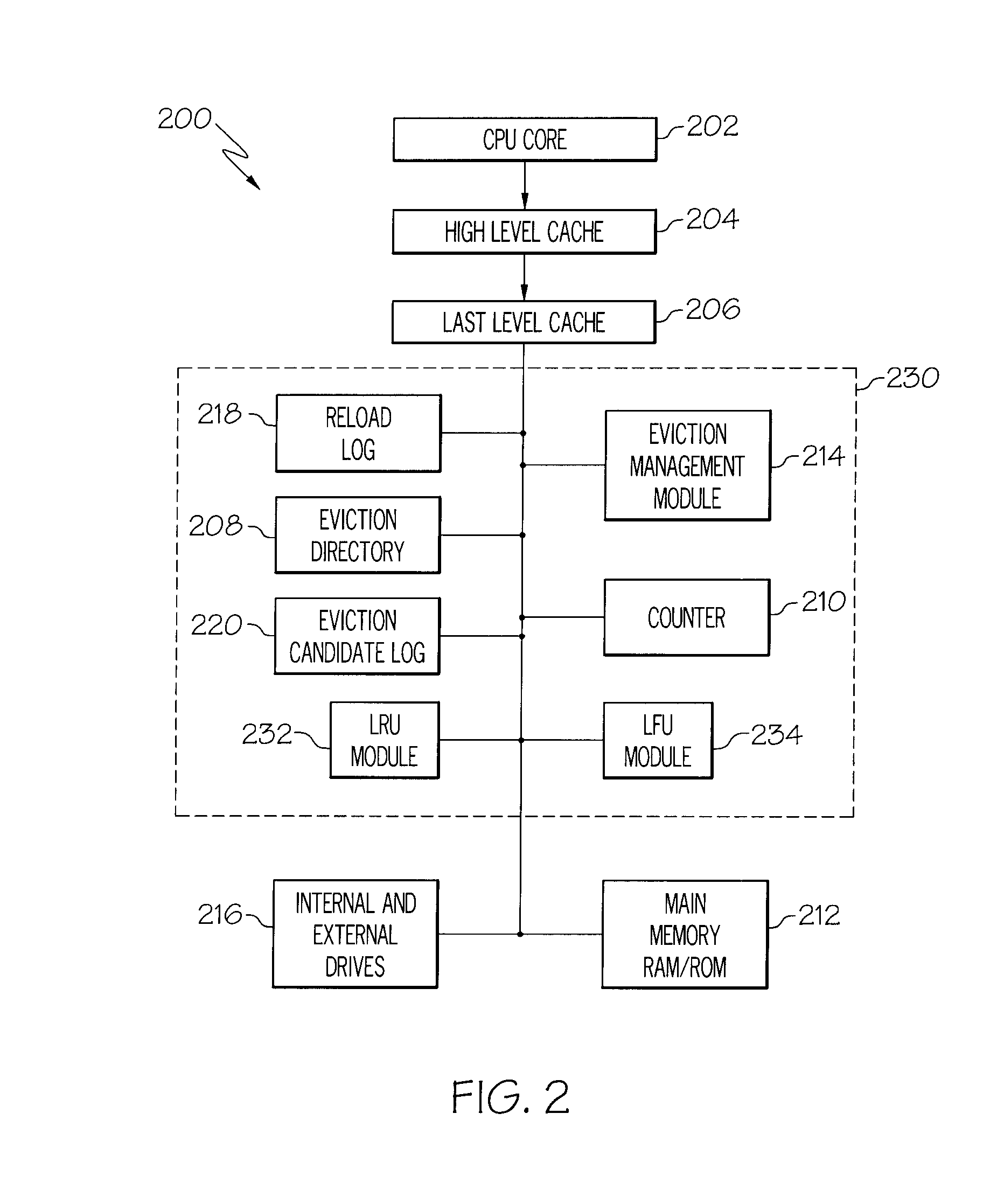
[0012]The problems identified above are in large part addressed by the apparatuses systems, methods, and arrangements disclosed herein to reduce the frequency of cache reloads by tracking the number of times that a particular line of cache has been evicted from cache or alternately has been reloaded into cache. The lines currently in cache can be ranked based on how many times the line has been evicted from cache. When additional cache capacity is required, the lines in cache that have never been evicted or have been evicted the fewest times can be selected for eviction. This can be distinguished from an LRU system where the eviction is based on usage when the line is in cache and not the number of times the line is needed and not stored in cache. The cache management / logging system disclosed herein can work in cooperation with an LFU algorithm or a LRU algorithm or other algorithm where these algorithms can utilize the directory of evicted cache line to help further reduce the cache miss rate and improve overall system performance.

Problems solved by technology

Transfer of data between the processor and external memory is relatively slow compared to the speed at which the microprocessor can perform data processing internally.
Consequently, the processor may be idle waiting for data to be retrieved from memory or waiting for data to be written to the memory.
When a lot of data is being transferred, say from one location to another in the system, processor idle time can occur during the majority of clock cycles.
In systems with large read and write delay times, the processor and other system resources can be idle over half of the time.
Such inefficiencies are generally unacceptable and consumer demands dictate that computer system designs address such inefficiencies.
However, cache is relatively small and typically can only store a small fraction of what can be stored in main memory.
When a processor executes an instruction that requests data or an instruction, the processor can first check to see if the requested line is already cache and if such a line is valid, (data can become invalid).
In traditional cases, the cache may not immediately notify the other functional block that the miss has occurred and may opt to send instruction to memory for retrieval of the requested line, again sacrificing valuable processor time.
This increase in the amount of code data required for processor operation puts more pressure on 64 bit cache systems that have not grown proportionally with the 64 bit core processor, and the result of this change is more frequent eviction of cache lines in such systems.
This higher rate of cache evictions associated with 64 bit cache systems significantly increases the cache miss rate (or miss per instruction).
As stated above, when a miss occurs, the processor must fetch data / code lines from main or system memory sacrificing valuable time.
This loss of time occurs because often, the line of code / data desired by the processor has been evicted in previous clock cycles due to capacity conflicts.
The resulting retrieval from non-cache memory systems will cause a relatively long idle period for the processor and other system components and this cache miss rates significantly degrades system efficiency.
This decreased efficiency leads to secondary issues such as increased power consumption, increased bus traffic, and generally degradation of overall system performance.
Most 64 bit processor architectures simply accept the increase in cache misses as an uncorrectable phenomenon, even though significant system degradation can be attributed to such failure to mange.
While this approach leads to very efficient utilization of the cache's capacity, it requires complex overhead processes and hardware.
The overhead incurred is rarely worth the effort required and only pays off if cache misses are many orders of magnitude more expensive than a cache hit.
Even hard disk caches where the disparity between hit and miss is a factor of about 1,000, LFU topologies may not achieve significantly better performance than LRU topologies.

Method used


Image

  • Systems and Arrangements for Cache Management
  • Systems and Arrangements for Cache Management
  • Systems and Arrangements for Cache Management

Examples


Embodiment Construction

[0024]The following is a detailed description of embodiments of the disclosure depicted in the accompanying drawings. The embodiments are in such detail as to clearly communicate the disclosure. However, the amount of detail offered is not intended to limit the anticipated variations of embodiments; on the contrary, the intention is to cover all modifications, equivalents, and alternatives falling within the spirit and scope of the present disclosure as defined by the appended claims. The descriptions below are designed to make such embodiments obvious to a person of ordinary skill in the art.

[0025]While specific embodiments will be described below with reference to particular configurations of hardware and / or software, those of skill in the art will realize that embodiments of the present invention may advantageously be implemented with other equivalent hardware and / or software systems. Aspects of the disclosure described herein may be stored or distributed on computer-readable med...


PUM


Abstract

A method for cache management is disclosed. The method can assign or determined identifiers for lines of binary code that are, or will be stored in cache. The method can create a cache directory that utilizes the identifier to keep an eviction count and/or a reload count for cached lines. Thus, each time a line is entered into, or evicted from cache, the cache eviction log can be amended accordingly. When a processor receives or creates an instruction that requests that a line be evicted from cache, a cache manager log can identify a line, or lines of binary code to be evicted based on data by accessing the cache directory and then the line(s) can be evicted.

Description

FIELD OF INVENTION[0001]The present disclosure is in the field of processors and particularly to management of cache memory contents associated with processors.BACKGROUND[0002]Most modern computer systems include some form of a processor and smaller computer systems typically utilize a microprocessor. In operation, a processor will typically retrieve instructions from memory and execute the instructions to process data. The majority of memory within a modern computer system is typically relatively large, and thus due to design requirements the majority of memory is nearly always physically located external to the integrated circuit that contains the processor. Thus, a processor will move data about the computer system, storing and retrieving data from memory when needed. More particularly, the processor can read data from main memory and write data to main or system memory that is external to the processor according to operating instructions.[0003]Transfer of data between the proces...

Claims


Application Information

Patent Timeline
Patent Type & Authority Applications(United States)
IPC IPC(8): G06F12/08
CPCG06F12/122G06F12/121
Inventor KORNEGAY, MARCUS L.PHAM, NGAN N.
Owner IBM CORP
Why Eureka
Try Eureka