Ultrasonic inspection method

a technology of ultrasonic and inspection method, which is applied in the direction of analysing solids using sonic/ultrasonic/infrasonic waves, measuring devices, instruments, etc., can solve the problems of complex curved components and welds, significant portion of these welds are neither flat nor smooth, and no ultrasonic inspection method is availabl

Active Publication Date: 2008-05-29
BWXT NUCLEAR OPERATIONS GRP
View PDF8 Cites 24 Cited by
  • Summary
  • Abstract
  • Description
  • Claims
  • Application Information

AI Technical Summary

Benefits of technology

[0009]The present invention addresses the deficiencies in the known art and is drawn to a method for ultrasonically inspecting components with wavy or uneven surfaces. A multi-element array ultrasonic transducer is operated with a substantial fluid layer, such as water at least several ultrasonic wavelengths thick, between the array transducer and the component surface. This fluid layer may be maintained by immersing the compon

Problems solved by technology

For example, in the commercial nuclear reactor industry there are many complex curved components and welds.
Field experience gained to date with these procedures shows that a significant portion of these welds are neither flat nor smooth.
Components with curved, wavy, or irregular surfaces have long been a challenge for ultrasonic testing.
However, when the surface profile varies in unknown ways along the surface prior to inspection, no method has been available to perform ultrasonic inspection.
However, it does not incorporate the ability to correct the aberration in the ultrasonic beam caused by an uneven surface profile over the width of the ultrasonic beam.
This restriction is very limiting since, as seen in FIG. 2, even a 1.5 inch radius of curvature causes severe beam distortion on a typical ultrasonic beam.
However, maintaining sufficient contact between the probe elements and the part surface to coup

Method used


Image

  • Ultrasonic inspection method
  • Ultrasonic inspection method
  • Ultrasonic inspection method

Examples


Embodiment Construction

[0016]While the inventive inspection method may be accomplished in at least three different ways, there are some common areas to each method.

[0017]The first common area is that it is preferable to use a multi-element array ultrasonic probe.

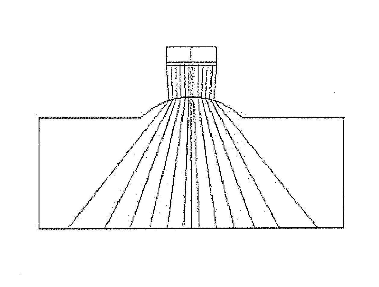
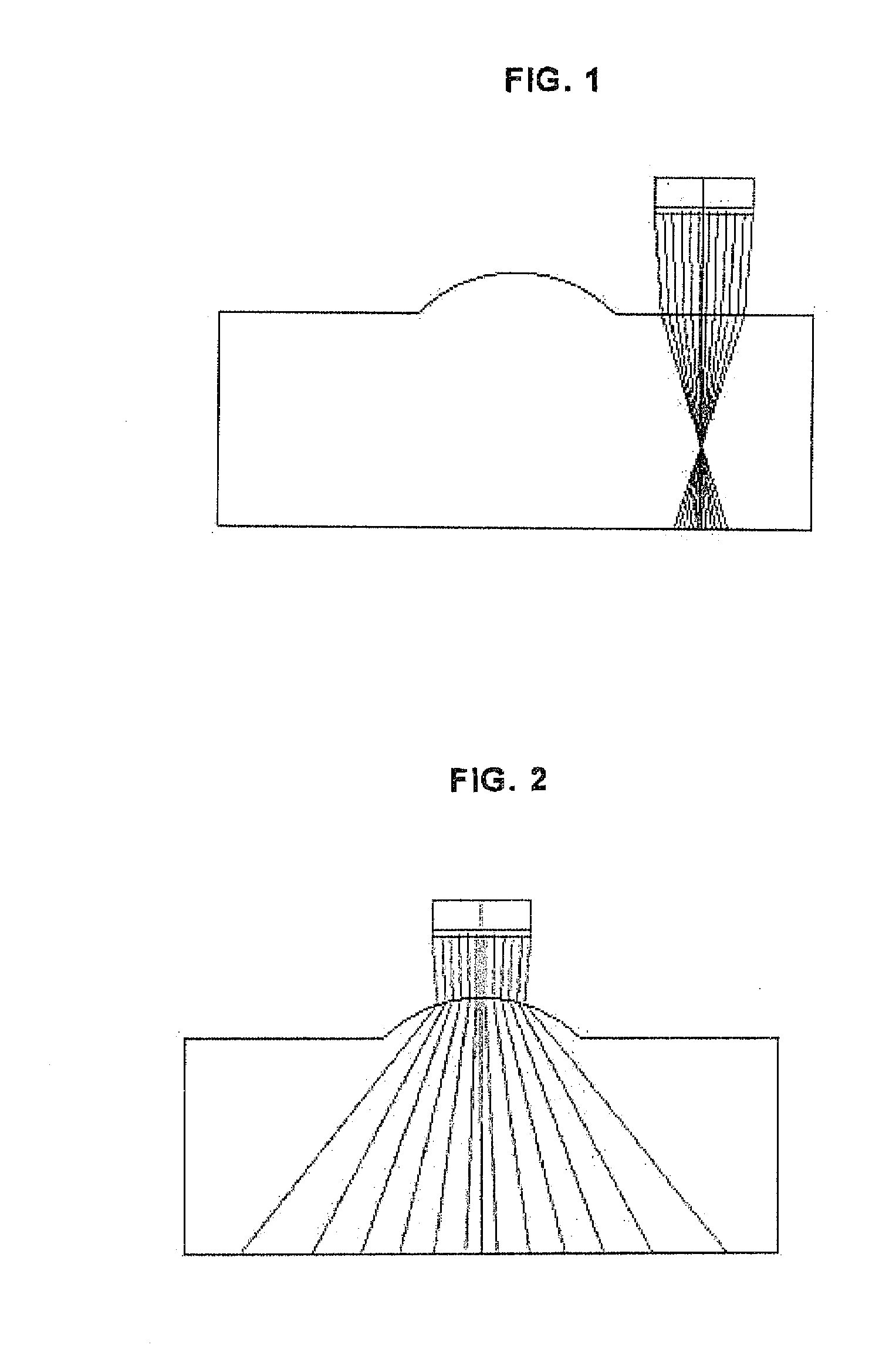
[0018]Another common area is that the probe is separated from the component to be inspected by a substantial fluid path. The fluid may be water or a gel, but is preferably water as this is easiest to work with. Current ultrasonic transducer inspections are typically carried out in a manner wherein the transducer is coupled to the component being inspected by a fluid or gel that is less than a few thousandths of an inch thick, which means that the transducer is essentially almost touching the component. Thus, for the purposes of the invention, a substantial fluid path is intended to be at least several ultrasonic wavelengths between the transducer and component such that there is a space between the transducer and component that allows a relatively...


PUM


Abstract

A method for ultrasonically inspecting components with wavy or uneven surfaces. A multi-element array ultrasonic transducer is operated with a substantial fluid layer, such as water, between the array transducer and the component surface. This fluid layer may be maintained by immersing the component in liquid or by using a captive couplant column between the probe and the component surface. The component is scanned, measuring the two dimensional surface profile using either a mechanical stylus, laser, or ultrasonic technique. Once an accurate surface profile of the component's surface has been obtained, data processing parameters are calculated for processing the ultrasonic signals reflected from the interior of the component that eliminate beam distortion effects and reflector mis-location that would otherwise occur due to the uneven surfaces.

Description

FIELD AND BACKGROUND OF INVENTION[0001]The invention is generally related to inspection of component parts and, more particularly, to the ultrasonic inspection of component parts.[0002]Components with complex shaped surfaces are common throughout industrial and government operation. Many times, the precise shape of these surfaces is not known prior to the need to perform an inspection. For example, in the commercial nuclear reactor industry there are many complex curved components and welds. Currently available qualified methods and procedures for performing ultrasonic (UT) examination of pipe welds from the outside surface are applicable only to geometries that are essentially flat and smooth. Field experience gained to date with these procedures shows that a significant portion of these welds are neither flat nor smooth. Typical field conditions encountered by UT examiners include variations in weld crown conditions and a range of other surface irregularities such as diametrical w...

Claims


Application Information

Patent Timeline
IPC IPC(8): G01N29/04
CPCG01N29/265G01N29/28G01N29/4463G01N2291/106G01N29/44G01N29/00G01N29/04
Inventor MACLAUCHLAN, DANIEL T.COX, BRADLEY E.
Owner BWXT NUCLEAR OPERATIONS GRP
Why Eureka
Try Eureka