Ultrasonograph

a technology of ultrasonograph and harmonic imaging, which is applied in the field of ultrasonograph, can solve the problems of deteriorating resolution, undesirable, and the degree of echo signal received from a deep portion, so as to improve the harmonic imaging of tissue without lowering the resolution

Inactive Publication Date: 2011-10-25
HITACHI LTD
View PDF18 Cites 20 Cited by
  • Summary
  • Abstract
  • Description
  • Claims
  • Application Information

AI Technical Summary

Benefits of technology

[0008]Accordingly, in comparison with a conventional case where a waveform having a frequency f0 is transmitted while its polarity is alternated, a frequency spectrum of the received signal after phasing and addition changes, whereby a component in a frequency band between f0 and 2f0 can be emphasized. Because the component in this frequency band has a frequency lower than 2f0, it is scarcely affected by attenuation, and so the penetration is desirable. Accordingly, by extracting this frequency component to generate an image based thereon, the penetration in the tissue harmonic imaging can be improved without lowering f0, i.e., without lowering the resolution.

Problems solved by technology

However, because the frequency of the harmonic component in an ultrasound signal is higher than that of the fundamental component, the harmonic component is sensitive to attenuation of the signal during propagation.
Accordingly, the degree of an echo signal received from a deep portion, i.e. the penetration, is undesirable.
However, the resolution is deteriorated, as is generally known.

Method used


Image

  • Ultrasonograph
  • Ultrasonograph
  • Ultrasonograph

Examples


embodiment 1

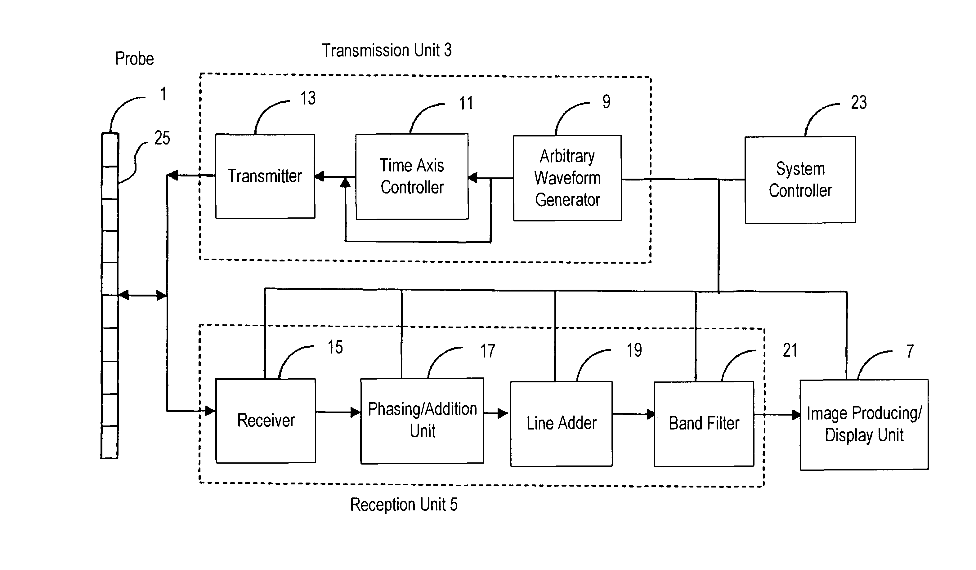
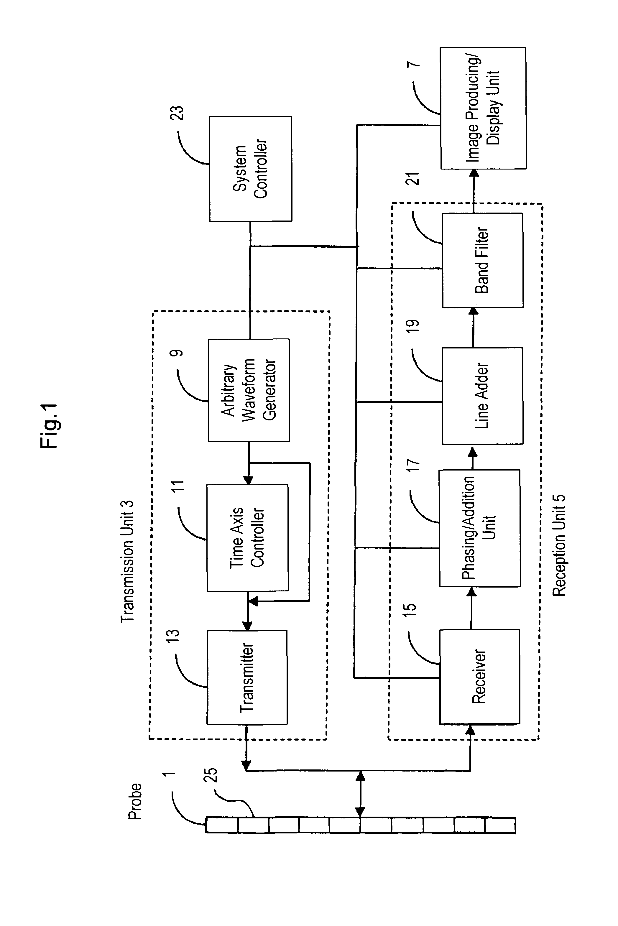
[0025]Hereinafter, an ultrasound diagnostic apparatus according to a first embodiment of the present invention will be described. FIG. 1 is a block diagram showing the structure of the ultrasound diagnostic apparatus according to this embodiment. As shown in FIG. 1, the ultrasound diagnostic apparatus includes an ultrasound probe 1, a transmission unit 3 for transmitting an ultrasound signal to an object to be examined (not shown in the figure) via the ultrasound probe 1, a reception unit 5 for receiving a received signal including an echo signal from the object via the ultrasound probe 1 and for processing the received signal, and an image producing / display unit 7 for generating and displaying a diagnostic image on the basis of the received signal processed by the reception unit 5. The image producing / display unit 7 includes a video processing unit for performing detection, compression, and the like, a Doppler processing unit, and a scan converter, which are not shown in the figure...

embodiment 2

[0051]Next, a second embodiment of the ultrasound diagnostic apparatus according to the present invention will be described. The same points as those, enumerated in the description of the first embodiment will not be mentioned, again, and only the differences will be described. The ultrasound diagnostic apparatus according to this embodiment is characterized in that the amplitude of both the first waveform and the second waveform is changed. That is, this embodiment is characterized in that the amplitude of waveform in the first cycle of the first waveform and the second waveform is respectively preset to be larger than that of the subsequent waveform.

[0052]An example of the first waveform and the second waveform having a varying frequency and amplitude and the frequency spectrum of transmitted signal and received signal will be described with reference to FIGS. 5a and 5b showing the simulation results thereof. FIG. 5a is a graph presenting the first waveform and the second waveform...

embodiment 3

[0059]Next, a third embodiment of the ultrasound diagnostic apparatus according to the present invention will be described. Here again, the same points as those enumerated in the description of the first embodiment will not be mentioned again, and only the differences will be described.

[0060]FIG. 6 is a block diagram showing the structure of an ultrasound diagnostic apparatus according to this embodiment. As shown in FIG. 6, the ultrasound diagnostic apparatus includes an ultrasound probe 31 having a plurality of ultrasound transducers or an ultrasound transducer array (not shown), a pulse inversion control unit 33 for controlling a signal transmitted to an object to be examined (not shown) via the ultrasound probe 31, and a transmitted wave phasing circuit 35 for generating a transmitted wave in response to a command from the pulse inversion control unit 33 and the driving ultrasound probe 31. The transmission phasing circuit 35 has a transmission timing generating circuit, a trans...


PUM


Abstract

An ultrasound diagnostic apparatus includes an ultrasound probe, a transmission unit for transmitting an ultrasound signal to an object to be examined via the ultrasound probe, a reception unit for processing a signal received by the ultrasound probe, and an image generating unit for generating an image on the basis of the received signal processed by the reception unit, wherein the transmission unit has a function of transmitting the ultrasound signals with varying frequency plural times in an identical direction at predetermined time intervals. The ultrasound signal transmitted plural times includes a first waveform in which the frequency increases and a second waveform in which the frequency decreases, and the reception unit has a function of phasing and adding received signals respectively corresponding to the first waveform and the second waveform, whereby, in tissue harmonic imaging, the penetration is improved, while the resolution is maintained.

Description

TECHNICAL FIELD[0001]The present invention relates to an ultrasound diagnostic apparatus, and, more particularly, to an ultrasound diagnostic apparatus for imaging a harmonic component that is generated when ultrasound is propagated inside a body of an object to be examined.BACKGROUND OF THE INVENTION[0002]An ultrasound diagnostic apparatus is designed to transmit an ultrasound signal inside an object to be examined and to obtain information available in diagnosis, e.g. a tomographic image, on the basis of a received signal, including an echo signal of the transmitted signal. It has been reported that, in the technique of displaying a tomographic image, a high-contrast image can be obtained by imaging a harmonic component (e.g. frequency 2f0 or 3f0) as opposed to a fundamental component (frequency f0) of the transmitted signal. An imaging method of this type is referred to as “Tissue Harmonic Imaging.”[0003]The above-described harmonic component is generated due to nonlinear distort...

Claims


Application Information

Patent Timeline
Patent Type & Authority Patents(United States)
IPC IPC(8): A61B8/14A61B8/00G01S15/89
CPCA61B8/00G01S15/8954G01S15/8963G01S7/52038
Inventor OKADA, KAZUTAKAKANDA, HIROSHIOTAKE, TSUYOSHIKIMURA, TSUYOSHIHAYASHI, TATSUYA
Owner HITACHI LTD
Why Eureka
Try Eureka