
Oblique veneer laminated material and method of manufacturing the same

a laminated material and plywood technology, applied in the field of laminated lumber, can solve the problems of wasting substantially half of the material, not seeing plywood in the actual market, and little consideration of the possibility of plywood or veneer laminated board of the above-described structur

Inactive Publication Date: 2008-05-29
SHIMANE PREFECTURAL GOVERNMENT MATSUE
View PDF1 Cites 4 Cited by
  • Summary
  • Abstract
  • Description
  • Claims
  • Application Information

AI Technical Summary

Benefits of technology

The present invention provides a solution for addressing issues with traditional laminated veneer lumber by creating diagonal laminated veneer lumber with multiple layers of veneer that are joined together using adhesive. The veneer sheets are cut from a rotary-cut veneer sheet and joined at the edges to form a band of joined veneer. The band of joined veneer is then divided into smaller sections to create the final laminated veneer lumber. The layers of veneer are oriented diagonally in opposite directions at an angle between 30-60 degrees. This creates a stronger and more stable laminated veneer lumber that is resistant to splitting and cracking.

Problems solved by technology

However, no such plywood is seen in actual market that is strengthened as described above.
A decisive reason for such disuse is that cutting the existing plywood boards for production of the above plywood board will waste substantially half of the material.
Thus, even the possibility of the presence of plywood or veneer laminated board of the above-described structure has been very little considered.
However, this method of manufacturing plywood is disadvantageous in terms of labor cost and material cost.
(5) Cedar that is one of the typical species of wood in Japan has been suffering from sluggish demand.

Method used


Image

  • Oblique veneer laminated material and method of manufacturing the same
  • Oblique veneer laminated material and method of manufacturing the same
  • Oblique veneer laminated material and method of manufacturing the same

Examples


Embodiment Construction

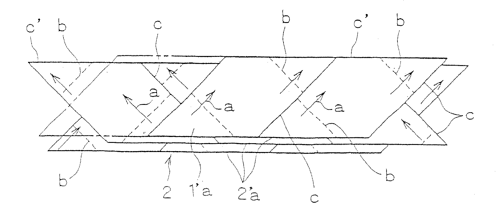
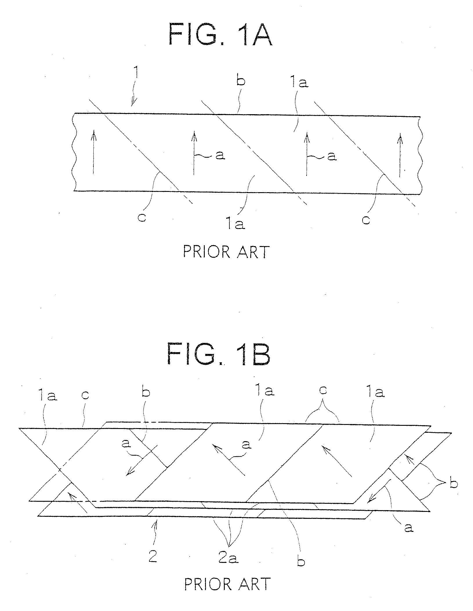
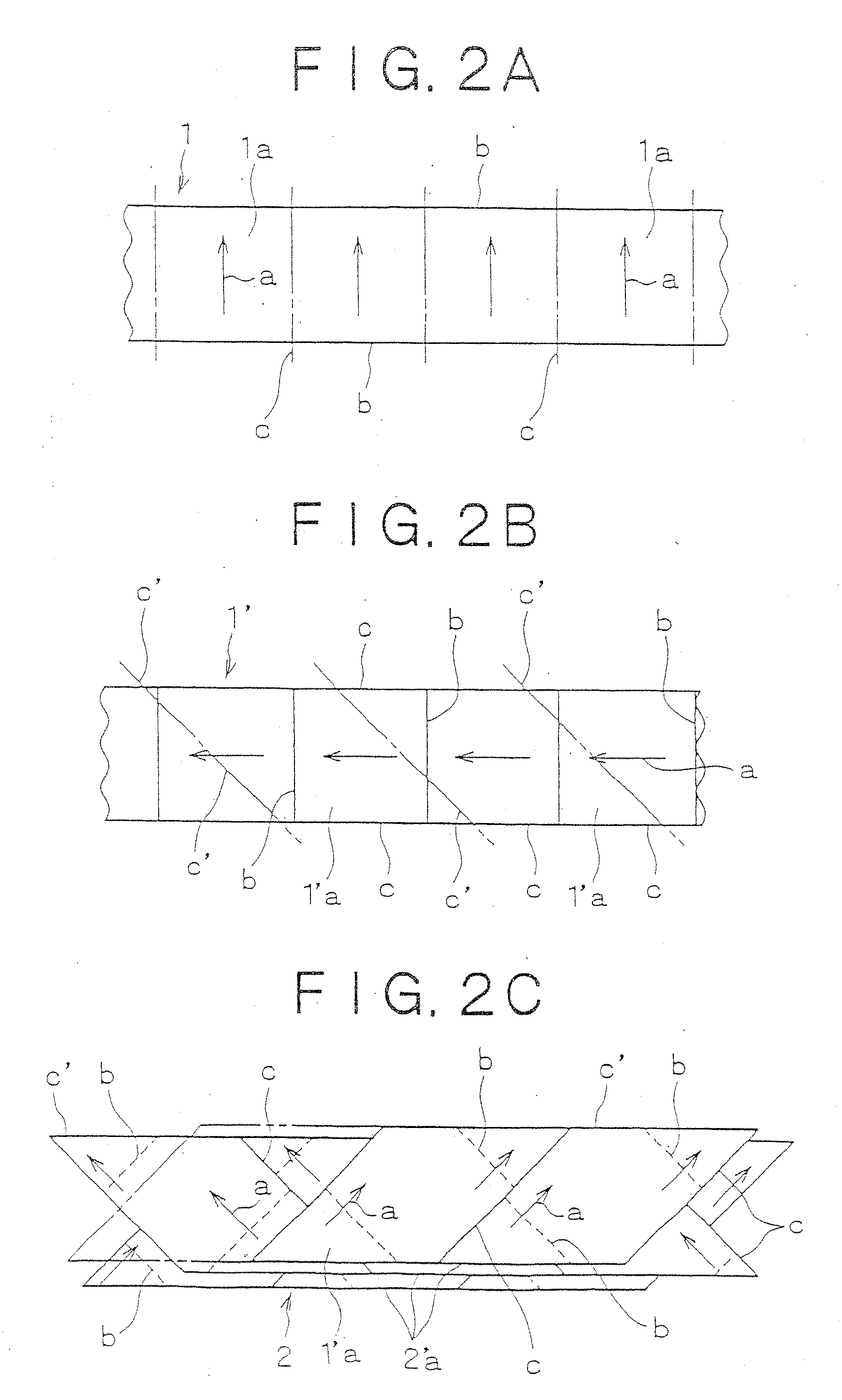
[0026]For better understanding of the present invention, reference is made to FIG. 1 which shows the steps of clipping a sheet of veneer 1 which has been rotary-cut, for example, by a rotary lathe and then laminating the clipped veneer sheets 1a together in know method of manufacturing diagonal laminated veneer lumber.

[0027]As is well known in the art, the rotary-cut veneer sheet 1 has a longitudinal dimension as measured along the wood grain which is oriented substantially perpendicularly to the opposite longitudinal ends b of the veneer sheet 1 as indicated by symbol a in FIG. 1(A). The veneer sheet 1 is clipped along cutting lines c spaced at a predetermined interval and extending diagonally at an angle in either direction with respect to the longitudinal ends b (or at about 45° downwardly leftward as seen in the plan view in the illustrated example) into a plurality of substantially lozenge-shaped veneer sheets 1a, as shown in FIG. 1(A).

[0028]The lozenge-shaped veneer sheet 1 ma...


PUM

PropertyMeasurementUnit
angleaaaaaaaaaa
angleaaaaaaaaaa
angleaaaaaaaaaa

Abstract

A veneer laminated material formed by improving a laminated material formed in a plate or column shape by stacking a plurality of sheet-like veneers overlapping with each other and adhering them to each other, and a method of manufacturing the veneer laminated material. The method comprises the steps of forming the veneers into parquet-like veneers formed by longitudinally arranging the plurality of divided small veneer pieces in a parquetry pattern continuously with each other, intersecting the fiber directions of the parquet-like veneers aslant with the longitudinal side ends of the parquet-like veneers, and laminating and forming the veneer laminated material by arranging the fiber directions of the parquet-like veneers adjacent to each other in a laminated layer cross section so as to be reversed to each other and intersected with each other. The fiber directions of the small veneer pieces may be intersected with the cut sides of the small veneer pieces or the fiber directions may be set in the generally same directions as the direction of the cut sides of the small veneer pieces.

Description

FIELD OF THE INVENTION[0001]The present invention relates to laminated veneer lumber of diagonal type in which veneer sheets are glued or laminated together with the wood grain thereof oriented diagonally or obliquely with respect the lateral sides of the lumber (such laminated veneer lumber may be referred to as “diagonal LVL”). The invention relates also to a method of manufacturing such diagonal laminated veneer lumber.BACKGROUND OF THE INVENTION[0002]As the wood board which is made by laminating veneer sheets by adhesive, glued laminated wood such as laminated lumber, plywood having veneer sheets laminated together such that any two adjacent veneer sheets are arranged with the wood grain thereof oriented perpendicularly to each other, laminated veneer lumber (LVL) in which constituent veneer sheets are laminated together with the wood grain thereof extending parallel to each other, etc. have been known in the art.[0003]General demand for the wood board or panel is changing from ...

Claims


Application Information

Patent Timeline
Patent Type & Authority Applications(United States)
IPC IPC(8): E04B2/00B27D1/04B32B7/03B32B21/14
CPCB27D1/04B32B21/14Y10T428/24132Y10T428/187Y10T428/183Y10T428/18Y10T156/1052Y10T156/1075Y10T156/1066Y10T428/24066Y10T156/1093B32B7/03B32B3/14B32B7/12B32B21/13
Inventor OHATA, HIROSHI
Owner SHIMANE PREFECTURAL GOVERNMENT MATSUE
Learn More