
Motor

a motor and motor body technology, applied in the field of motors, can solve the problems of large structural modification limitations of stators, damage to stators, and inability to meet the needs of use, and achieve the effects of reducing cores, and insulators, simplifying the structure of stators, and reducing the structural limitations of stators

Inactive Publication Date: 2008-05-29
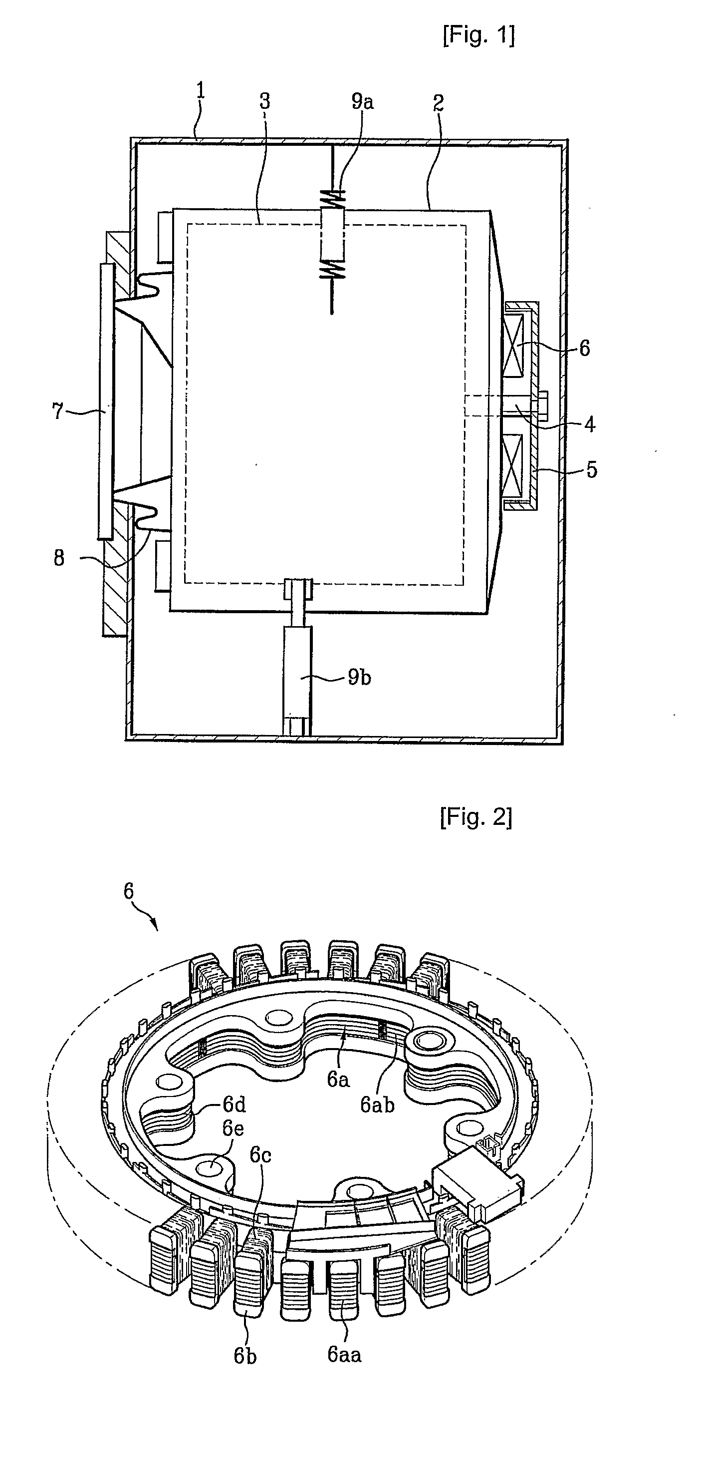
LG ELECTRONICS INC
View PDF6 Cites 46 Cited by
  • Summary
  • Abstract
  • Description
  • Claims
  • Application Information

AI Technical Summary

Benefits of technology

[0019]An object of the present invention devised to solve the above-mentioned problems lies in providing a motor which includes a stator having an improved structure, thereby being capable of obtaining a superior waterproofness.
[0020]Another object of the present invention is to provide a motor which is structured to reduce the structural limitations of the core and insulator thereof, and to enable the stator thereof to be easily and stably fixed to an appliance using the motor, for example, a washing machine.Technical Solution
[0022]In accordance with the present invention, the stator constituting the motor is enclosed by the molded member made of an insulating resin material. Accordingly, it is possible to substantially prevent water from penetrating toward the coils in the stator, and thus, to achieve an enhancement in waterproofness.
[0023]In addition, the coupling portion for the stator is formed at the molded member such that they are integral, during the injection molding process for the molded member. Accordingly, it is unnecessary to form coupling portions at the insulator and core. As a result, it is possible to simplify the structures of the stator, core, and insulator, to minimize the structural limitations of the stator, core, and insulator, and to easily and stably achieve the coupling of the stator.

Problems solved by technology

First, in the conventional motor, the coils of the stator are outwardly exposed. For this reason, when the motor is applied to an appliance using water, for example, a washing machine, there may be a problem in that water may come into contact with the stator unless the waterproofness of the motor is ensured, thereby causing the stator to be damaged.
Due to this structure, however, the structural modification of the core and insulator is greatly limited.
For example, where a spiral core is used for the core of the stator, in order to reduce the loss of the core material, it is necessary to form bolt-coupling holes in the insulator itself because it is difficult to form such bolt-coupling holes in the spiral core itself.
In this case, however, there is a problem in that it is impossible to form coupling members, which are adapted to couple the stator to the tub, at the inside of the core such that the coupling members are protruded from the core.
If coupling members are formed at the inside of the spiral core such that the coupling members are protruded from the spiral core, it is impossible to bend the core because the core has an excessively large width at regions where the protrusions are present, respectively.
As a result, the material and structure of the insulator are limited, so that the fabrication of the stator becomes more difficult.

Method used


Image

  • Motor
  • Motor
  • Motor

Examples


Embodiment Construction

[0035]Reference will now be made in detail to the preferred embodiments of the present invention, examples of which are illustrated in the accompanying drawings.

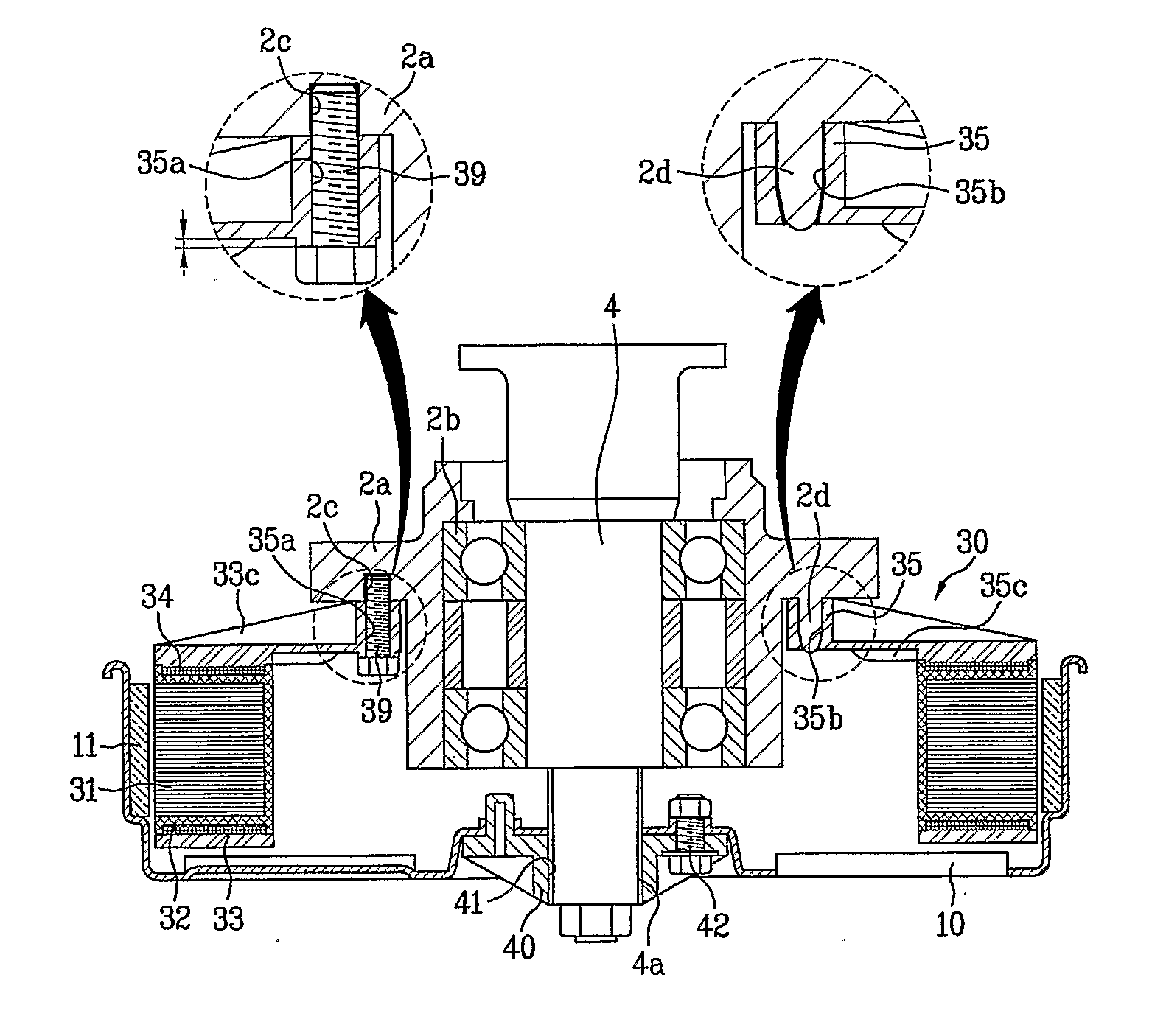
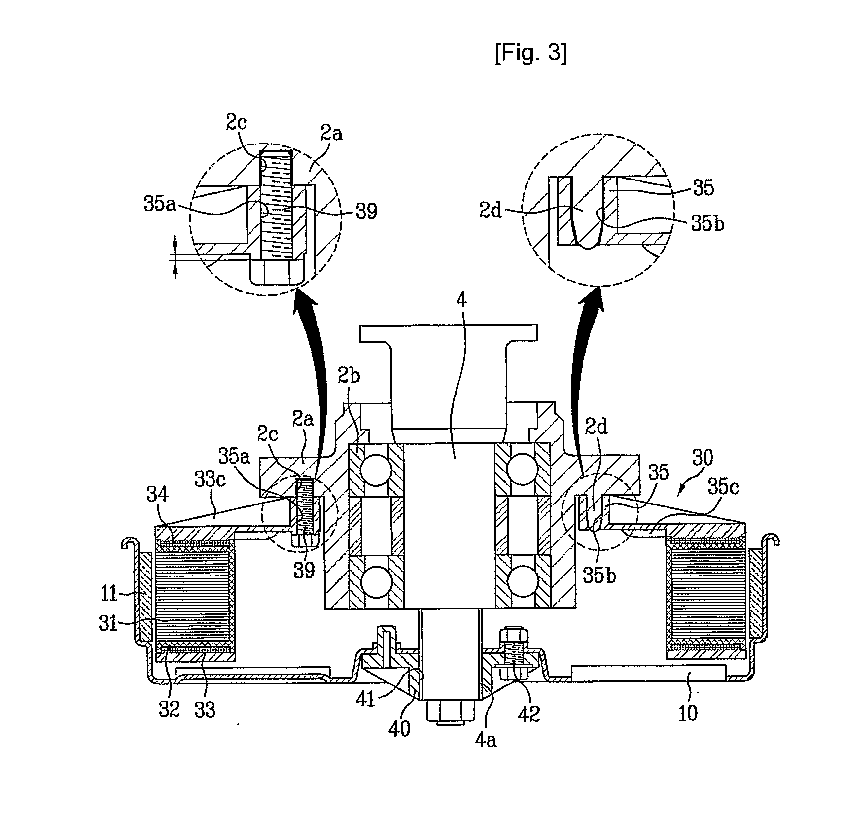
[0036]First, a motor according to an exemplary embodiment of the present invention will be described with reference to FIGS. 3 to 7.

[0037]For better understanding of the present invention, the following description will be given in conjunction with the case in which the motor of the present invention is applied to a drum washing machine. However, the motor of the present invention is also applicable to a pulsator washing machine, a dryer, an air conditioner, etc., equally or similarly to the drum washing machine.

[0038]As shown in FIGS. 3 and 4, a rotating shaft 4 is rotatably mounted at a central portion of the rear wall of a tub 2 (FIG. 1) in the washing machine. The rotating shaft 4 is rotatably supported by a bearing 2b fitted in a bearing housing 2a mounted to the rear wall of the tub 2.

[0039]A motor, which is adapted to...


PUM


Abstract

A motor adapted to rotate an element of an appliance, for example, a drum of a washing machine, is disclosed. The motor includes a rotating shaft which is rotatably mounted to a motor mounting member of an appliance, a rotor which includes magnets circumferentially arranged at a position radially spaced apart from a center of the rotating shaft by a predetermined distance such that N and S poles are alternately arranged, and a stator which includes a core made of metal, an insulator enclosing the core while allowing a surface of the core facing the magnets of the rotor to be outwardly exposed, the insulator being made of an insulating resin material, coils wound on the insulator, and a circular molded member formed in accordance with an insert molding method to enclose the insulator and the coils while allowing the surface of the core outwardly exposed through the insulator to be outwardly exposed.

Description

TECHNICAL FIELD[0001]The present invention relates to a motor, and more particularly, to a motor which includes a stator fixedly mounted to a washing machine or the like, the stator having an improved structure capable of achieving an improvement in waterproofness and mountability.BACKGROUND ART[0002]Generally, a motor is essentially used in a drum washing machine, a pulsator washing machine, a dryer, an air conditioner, or the like, to rotate a drum, a washing tub, a blowing fan, or the like.[0003]For example, in a drum washing machine, a motor is arranged at the rear of a tub such that the motor is directly coupled to a shaft of a drum. In this case, accordingly, the drive power of the motor is directly transferred to the drum. As a result, it is possible to achieve an increase in rotating force while reducing loss of drive power.[0004]An example of a conventional motor, which is applied to a drum washing machine, will be described in brief with reference to FIGS. 1 and 2.[0005]As...

Claims


Application Information

Patent Timeline
IPC IPC(8): H02K5/22H02K5/04H02K3/32H02K11/00
CPCH02K1/148H02K21/22H02K1/187A45D34/06A45D40/24A45D2034/002A45D2040/0006A45D2200/058
Inventor CHO, HUNG MYONGJEONG, SEONG HAIKIM, YEONG SOO
Owner LG ELECTRONICS INC
Learn More