Led driver

a technology of led driver and driver body, which is applied in the direction of electric variable regulation, process and machine control, instruments, etc., can solve the problems of increased thermal loss, increased thermal loss, and excess over the permitted loss at the constant current circuit par

Inactive Publication Date: 2008-05-29
SHARP KK
View PDF3 Cites 47 Cited by
  • Summary
  • Abstract
  • Description
  • Claims
  • Application Information

AI Technical Summary

Benefits of technology

[0011]To solve the problem described above, the present invention has been made, and it is an object of the invention to provide an LED driver capable of, while adopting a constant current driving method using a constant current circuit, easily minimizing unnecessary power consumption and respecting the permitted loss at the constant current circuit.

Problems solved by technology

Thus, if this difference is excessively larger than the voltage required at the constant current circuit part, the dissipation in the constant current circuit part increases, thus resulting in increased thermal loss.
Thus, such a difference between these two voltages is likely to become larger than the voltage required at the constant current circuit part, thus resulting in a high possibility of increased thermal loss.
However, in the circuit configuration shown in FIG. 10, even if an optimum resistance is selected for a maximum current driving the load LED, as a result of current fluctuation, there arises a current range where the loss at the constant current circuit part is large, which also causes a possibility of excess over the permitted loss at the constant current circuit part.

Method used


Image

  • Led driver
  • Led driver
  • Led driver

Examples


first embodiment

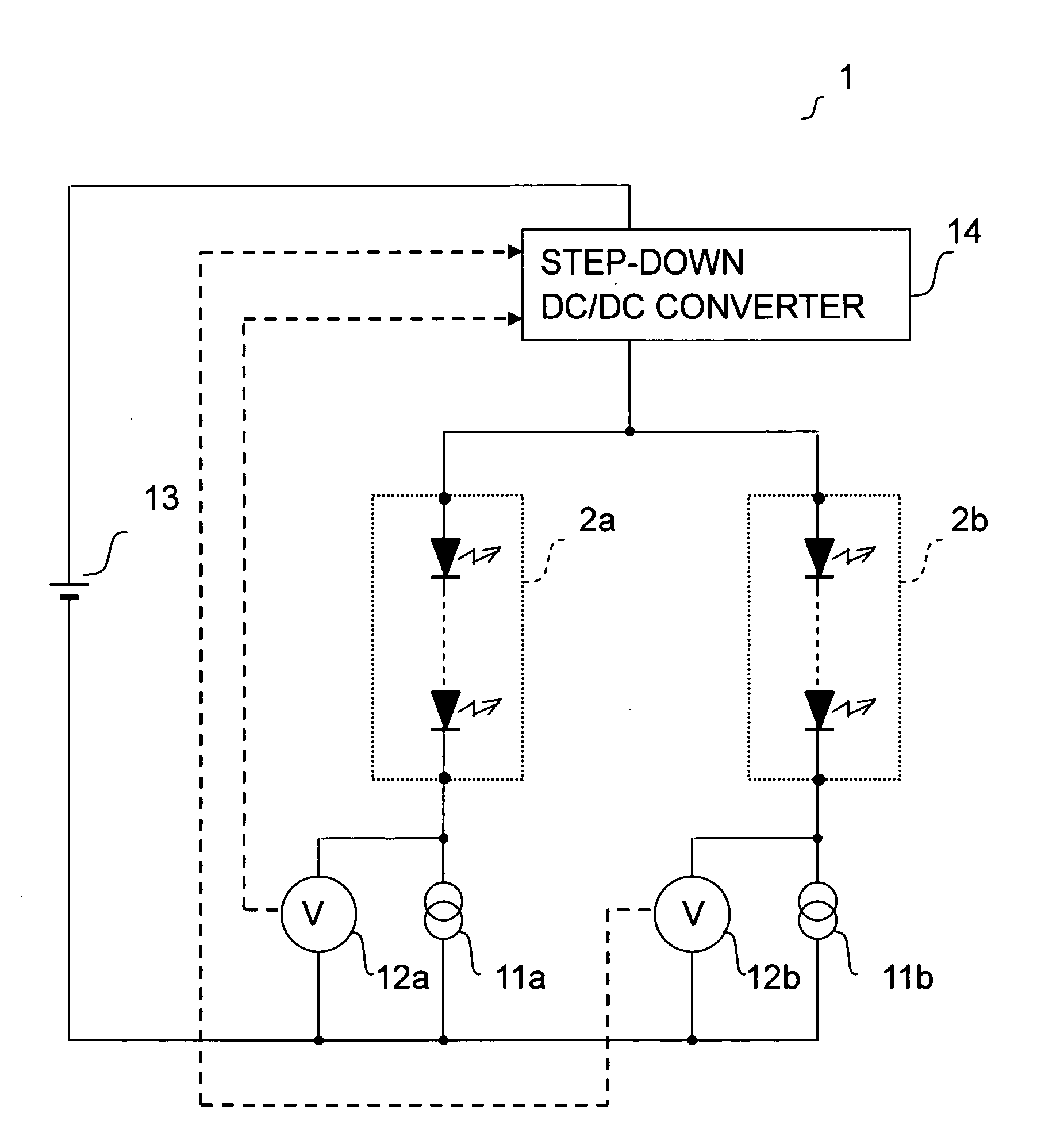
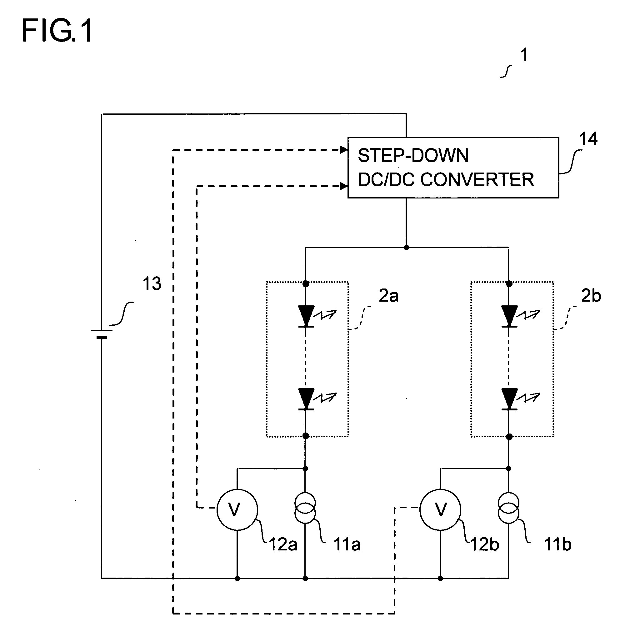
[0051]Configuration of an LED driver according to the first embodiment of the invention will be described with reference to FIG. 1. As in this figure, the LED driver 1 is provided with constant current circuit parts (11a and 11b), voltage detection parts (12a and 12b), a constant voltage source 13, and a step-down DC / DC converter 14. In the LED driver 1, as shown in FIG. 1, a first-line LED group 2a and a second-line LED group 2b are connected in parallel to each other.

[0052]More specifically, the first-line LED group 2a is connected between the downstream side of the step-down DC / DC converter 14 and the upstream side of the constant current circuit part 11a. The second-line LED group 2b is connected between the downstream side of the step-down DC / DC converter 14 and the upstream side of the constant current circuit part 11b.

[0053]The constant current circuit parts (11a and 11b) are each formed of a constant current circuit that adjusts a current flowing therethrough (that is, a cu...

second embodiment

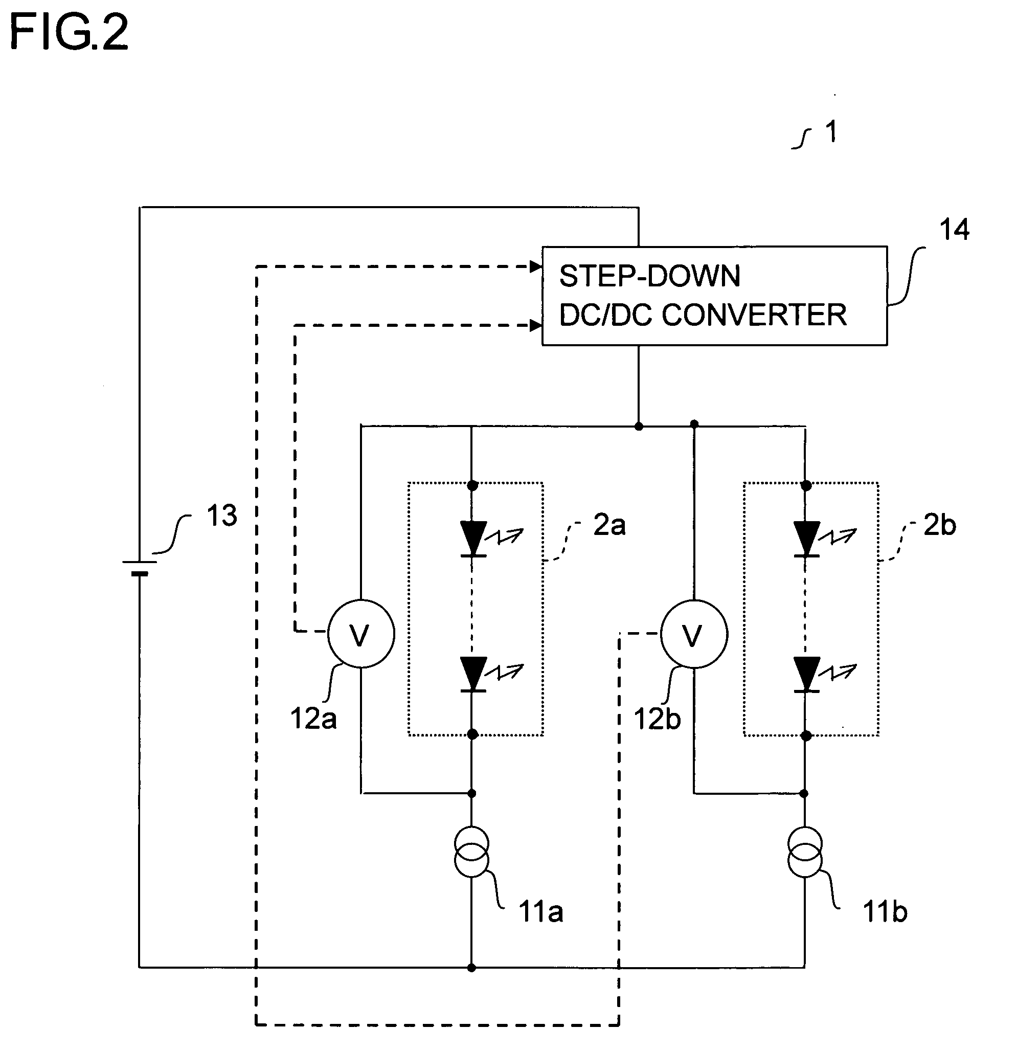
[0063]Next, configuration of an LED driver according to the second embodiment of the invention will be described with reference to FIG. 3. As in this figure, the LED driver 1 is provided with constant current circuit parts (11a and 11b), voltage detection parts (12a and 12b), a constant voltage source 13, a step-down DC / DC converter 14, switching connection parts (15a and 15b), and the like. In the LED driver 1, as shown in FIG. 3, a first-line LED group 2a and a second-line LED group 2b are connected in parallel to each other.

[0064]More specifically, the first-line LED group 2a is connected between the downstream side of the switching connection part 15a and the upstream side of the constant current circuit part 11a. The second-line LED group 2b is connected between the downstream side of the switching connection part 15b and the upstream side of the constant current circuit part 11b.

[0065]The constant current circuit parts (11a and 11b) have upstream sides thereof respectively co...

third embodiment

[0078]Next, configuration of an LED driver according to the third embodiment of the invention will be described with reference to FIG. 5. As in this figure, the LED driver 1 is provided with constant current circuit parts (11a and 11b), a constant voltage source 13, a step-down DC / DC converter 14, a switching connection part 15, and a dropper 16. In the LED driver 1, as shown in FIG. 5, a first-line LED group 2a and a second-line LED group 2b are connected in parallel to each other.

[0079]More specifically, the first-line LED group 2a is connected between the downstream side of the switching connection part 15 and the upstream side of the constant current circuit part 11a. The second-line LED group 2b is connected between the downstream side of the switching connection part 15 and the upstream side of the constant current circuit part 11b.

[0080]The constant current circuit parts (11a and 11b) have upstream sides thereof respectively connected to the LED groups (2a and 2b) and have d...


PUM


Abstract

An LED driver according to the present invention feeds an electric power to an LED circuit, which is either of a single LED or a plurality of LEDs serially connected together. The LED driver includes: a constant current circuit part serially connected to the LED circuit and adjusting a current flowing from an upstream to a downstream side thereof to a predetermined value; and a voltage adjustment part serially connected to the constant current circuit part and adjusting a potential difference between the upstream and downstream sides with a switching regulator. This therefore permits providing an LED driver capable of, while adopting a constant current driving method using a constant current circuit, easily minimizing unnecessary power consumption and respecting the permitted loss at the constant current circuit.

Description

[0001]This application is based on Japanese Patent Application No. 2006-318288 filed on Nov. 27, 2006, the contents of which are hereby incorporated by reference.BACKGROUND OF THE INVENTION[0002]1. Field of the Invention[0003]The present invention relates to an LED driver as a device for illuminating an LED.[0004]2. Description of Related Art[0005]Conventionally adopted as LED drivers for illuminating an LED (Light Emitting Diode) are those which employ a resistance driving method using a constant voltage source and a resistor and those which employ a constant current driving method using a constant current source. FIG. 9 shows a circuit example of the resistance driving method.[0006]The resistance driving method employs relatively simple structure, which can be achieved at low costs. However, the amount of a current flowing to the LEDs is influenced by a sum of voltage drop VF in LEDs acting as loads (hereinafter referred to as load LEDs) serially connected together. Thus, a variat...

Claims


Application Information

Patent Timeline
Patent Type & Authority Applications(United States)
IPC IPC(8): G09G3/14H05B41/36H01L33/00
CPCG09G3/14G09G2320/0633Y02B20/341H05B33/0815H05B33/0827G09G2330/021H05B45/375H05B45/46Y02B20/30
Inventor KATOH, SHUN-ICHI
Owner SHARP KK
Why Eureka
Try Eureka