

Input device
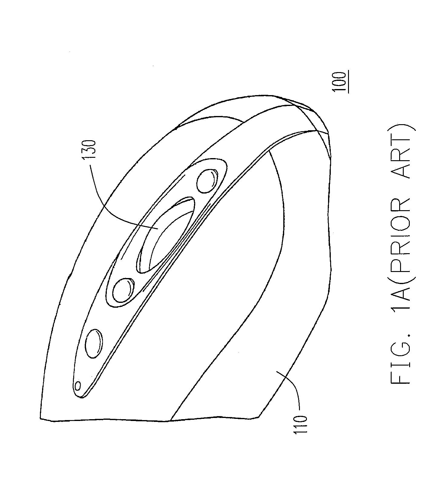
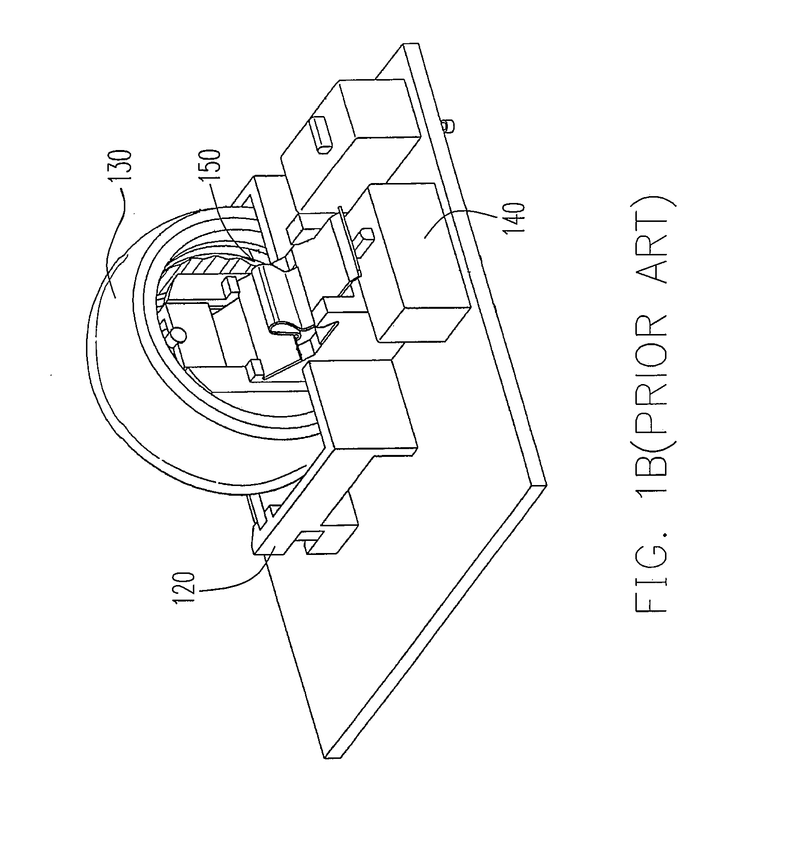
a technology of input device and actuator, which is applied in the field of input device, can solve the problems of increasing the difficulty of assembling l-shaped actuators, l-shaped actuators b>250/b> being more vulnerable to damage, and the conventional input device b>100/b> occupies a rather large volume, and achieves the effect of small volume, easy assembly and more durabl
- Summary
- Abstract
- Description
- Claims
- Application Information
AI Technical Summary
Benefits of technology
Problems solved by technology
Method used
Image

Examples
first embodiment
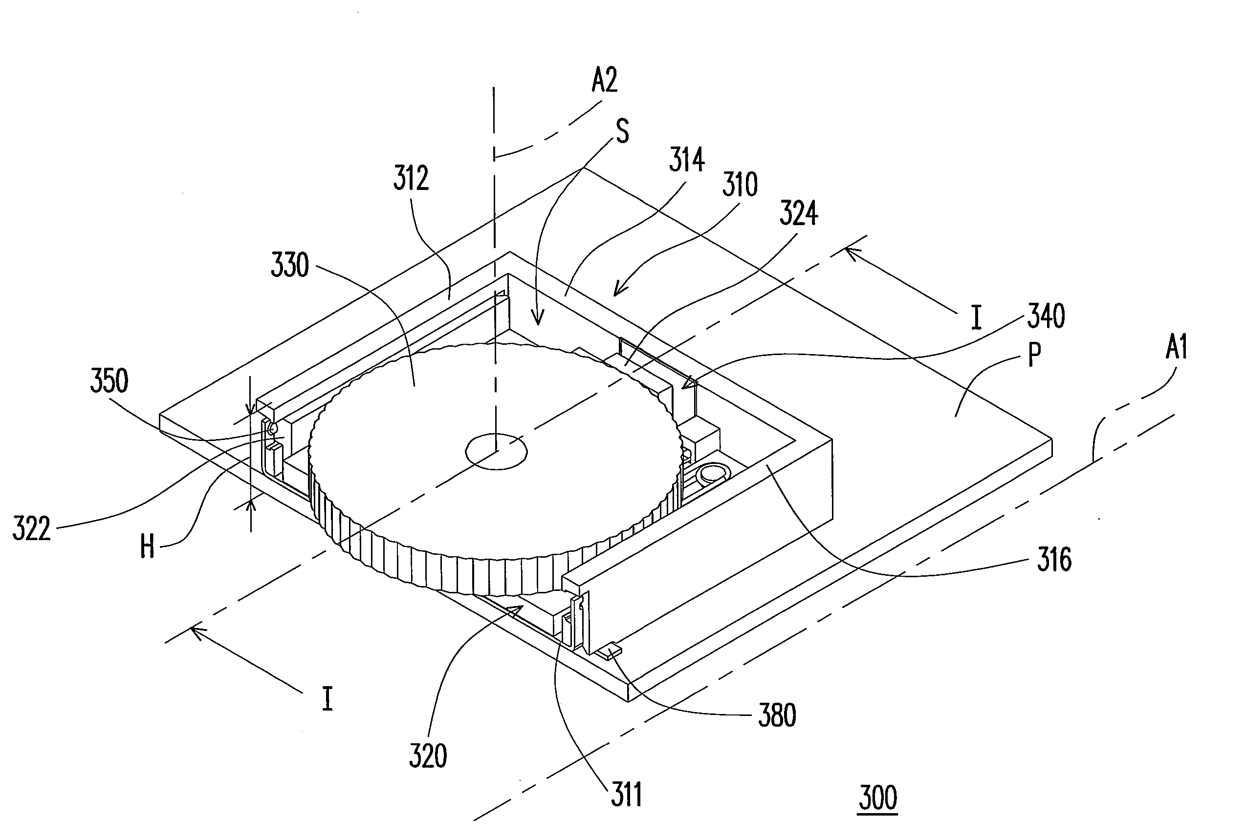
[0030]FIG. 3 is a schematic perspective view of an input device according to a first embodiment of the present invention. FIG. 4 is a schematic partial explosion view of the input device in FIG. 3. As shown in FIGS. 3 and 4, the input device 300 in the first embodiment is disposed on a circuit board P. The input device 300 includes a frame 310, a sliding base 320, a rotary wheel 330 and a switch 340. The sliding base 320 is slidingly connected to the frame 310. The sliding base 320 substantially slides linearly along a slide axis A1. The slide axis A1 is substantially parallel to the circuit board P. The rotary wheel 330 is revolvably affixed to the sliding base 320. The rotary wheel 330 substantially rotates around a rotation axis A2. The rotation axis A2 is substantially perpendicular to the circuit board P. In addition, the switch 340 is disposed on the frame 310. The rotary wheel 330 actuates the switch 340 through the sliding motion of the sliding base 320.
[0031]Because the rot...
second embodiment
[0044]FIG. 8 is a schematic perspective view of an input device according to a second embodiment of the present invention. The main difference between the input device 400 in the second embodiment and the input device 300 in the first embodiment is that the switch 440 of the second input device 400 is disposed on the sidewall 412 on the sliding path of the rotary wheel 430 or the sliding base 420. When the rotary wheel 430 slides along the slide axis A1 toward the interior of the frame 410, the rotary wheel 430 slides toward the interior of the frame 410 through the sliding base 420 and the edge of the rotary wheel 430 closest to the sidewall 412 will apply a pressure to the switch 440 to actuate the switch 440.
[0045]FIG. 9 is a schematic top view of the frame in FIG. 8. FIG. 10 is a schematic front view of the input device in FIG. 8. To facilitate the description, some local cross-sections are shown in FIG. 10. As shown in FIGS. 9 and 10, the input device 400 of the second embodime...
third embodiment
[0048]FIG. 11 is a schematic cross-sectional view of an input device according to a third embodiment of the present invention. The main difference between the input device 500 of the third embodiment and the input devices 300 and 400 in the foregoing embodiments is that the switch 540 of the input device 500 may be disposed on the bottom plate 511. Furthermore, the sliding base 520 has a bulge 529 disposed on its bottom surface 526. When the rotary wheel 530 is acted on by an external force along the slide axis A1 toward the interior of the frame 510, the rotary wheel 530 slides into the interior of the frame 510 through the sliding base 520 and the sliding motion of the sliding base 520 causes the bulge 529 to apply a pressure on the switch 540 to actuate the switch 540.
[0049]It should be noted that that bottom plate 511 have a conducting portion 511a and an insulating portion 511b in the present embodiment. The conducting portion 511a is electrically connected to the grounding por...
PUM
 Abstract
Description
Claims
Application Information