Video Signal Output Device And Method

a video signal and output device technology, applied in the field of video signal output devices and methods, can solve the problems of unsmooth moving images, possible overflow of reception-side buffers, and possible underflow of reception-side buffers, and achieve the effect of easy displaying moving images

Inactive Publication Date: 2008-05-29
ALPINE ELECTRONICS INC
View PDF9 Cites 16 Cited by
  • Summary
  • Abstract
  • Description
  • Claims
  • Application Information

AI Technical Summary

Benefits of technology

[0017]The present invention has been accomplished in view of the above problems involved in the related art, and it is accordingly an object of the present invention to provide a video signal output device and method capable of easily displaying moving images while synchronizing transmission-side data and reception-side data even if video data is asynchronously transferred to the reception side from the transmission side.

Problems solved by technology

In the case where the clocks differ between the transmission side and the reception side, if a clock rate on the transmission side is higher than that on the reception side, there is a possibility of the reception-side buffer overflowing.
If the overflow occurs, video data is partially destructed on the reception side, resulting in a problem of unsmooth moving images.
In contrast, if a clock rate on the transmission side is lower than that on the reception side, there is a possibility of underflow occurring in the reception-side buffer.
If the underflow occurs, video data cannot be displayed on the reception side, resulting in a problem of discontinuous moving images.
However, it is necessary to continuously monitor the buffer data amount to check an amount of data stored in the buffer in order to control a clock oscillation frequency, with the result that a device configuration is complicated.
However, its configuration is complicated and costly.
However, it is necessary to continuously monitor a buffer data amount to control a clock oscillation frequency, which puts a heavy burden on a CPU.

Method used


Image

  • Video Signal Output Device And Method
  • Video Signal Output Device And Method
  • Video Signal Output Device And Method

Examples


modified example 1

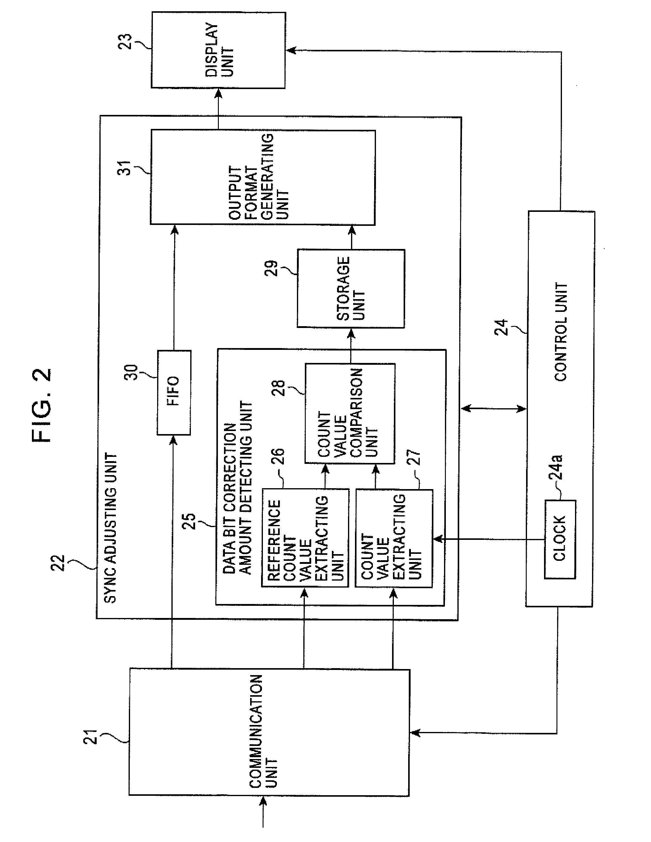
[0087]In the data bit correction of the above embodiment, a correction amount of data bits is calculated on the basis of a difference between a data bit amount of one frame of the clock 24a of the video signal output device 20 and a data bit amount of a reference format. In Modified Example 1, a correction amount of data bits is calculated on the basis of a data bit amount in one horizontal synchronous period.

[0088]The configuration of the synchronization adjustment unit is the same as in the above embodiment.

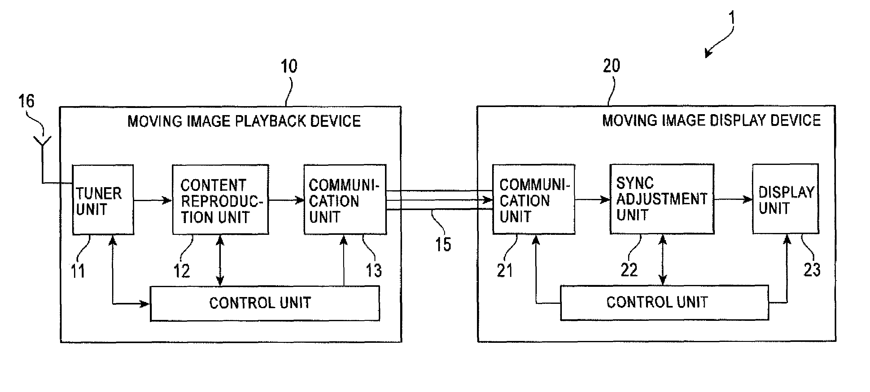
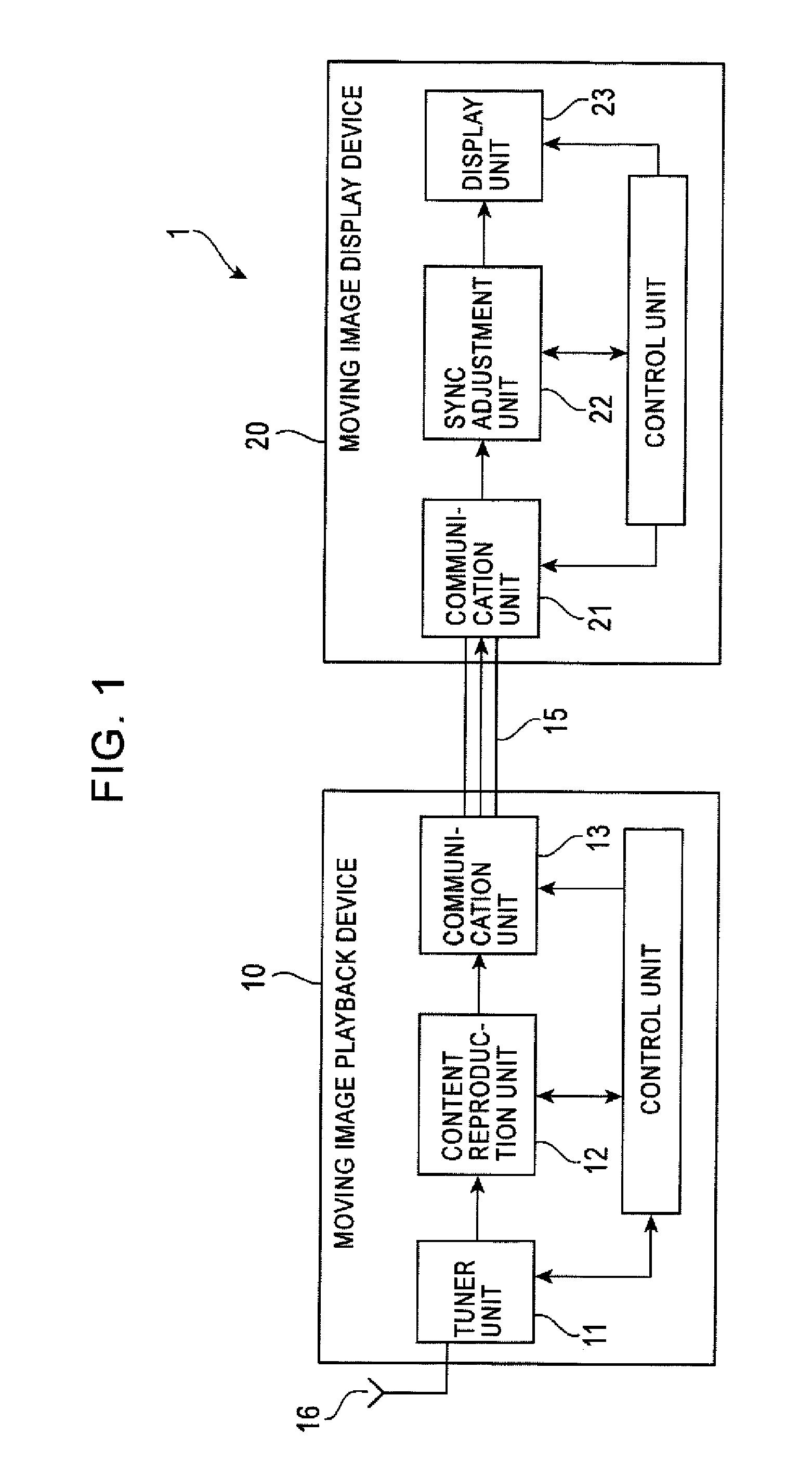
[0089]For example, the communication unit 13 of the moving image playback device 10 packetizes video data to be transmitted. If a packet generation period is longer than a horizontal synchronous period of video data, packets include horizontal synchronous signals. In particular, if two horizontal synchronous signals are included in one packet, a data bit correction amount can be detected on the basis of a horizontal scanning period.

[0090]First, as described in the above embodim...

modified example 2

[0094]In the data bit correction of the above embodiment, a correction amount of data bits is detected for the first one frame of video data received with the video signal output device 20, and data bits of subsequent frames are adjusted. In this modified example, the data bit correction amount is detected periodically, not for the first one frame.

[0095]As a result of comparing a data bit correction amount detected for the first frame with a data bit correction amount detected for a frame that appears after the elapse of a predetermined period, if the correction amount is changed, data bits are adjusted in accordance with the change.

[0096]For example, if the transmission-side device and the reception-side device are placed under different temperature conditions, a period necessary for stabilizing a clock frequency differs between the devices. Hence, a data bit correction amount varies in accordance with a measurement period. In such cases, a horizontal scanning line is adjusted in a...


PUM


Abstract

A video signal output device and method are capable of easily displaying moving images while synchronizing transmission-side data and reception-side data even if video data is asynchronously transferred to the reception side from the transmission side. A video signal output device for receiving video data transmitted from a transmitter in sync with a first clock through a communication unit, storing the video data in a storage unit, reading the video data from the storage unit in sync with a second clock, and displaying moving images on a display unit, includes a synchronization adjustment unit for detecting a video data correction amount in accordance with a reference video data amount in one vertical synchronous period and a video data amount of the second clock in one vertical synchronous period to adjust a predetermined horizontal scanning period in accordance with the video data correction amount. The synchronization adjustment unit may distribute the video data correction amount to a plurality of invalid horizontal scanning periods not contributing to the display of moving images and adjust the plurality of invalid horizontal scanning periods.

Description

BACKGROUND OF THE INVENTION[0001]1. Related Applications[0002]The present application claims priority to Japanese Patent Application Number 2006-317308, filed Nov. 24, 2006, the entirety of which is hereby incorporated by reference.[0003]2. Field of the Invention[0004]The present invention relates to a video signal output device and method, and more specifically to a video signal output device and method suitable for synchronous processing of video signals with a clock different from a clock on a transmission side.[0005]3. Description of the Related Art[0006]To transmit moving images in real time, for example, streaming-playback-based digital communications have been performed. In such digital communications, video signals are processed as follows.[0007]An analog video signal input to a transmitter through broadcasting or the like is converted into digital video data with an analog / digital converter and stored in a transmission-side buffer. For efficient utilization of a network ban...

Claims


Application Information

Patent Timeline
Patent Type & Authority Applications(United States)
IPC IPC(8): H04N5/10G09G5/00G09G5/18G09G5/391H04N7/173H04N21/433H04N21/442
CPCH04N5/10
Inventor KUBOTA, AKIHIRO
Owner ALPINE ELECTRONICS INC
Why Eureka
Try Eureka