
Three-dimensional shape measurement method and three-dimensional shape measurement apparatus

a three-dimensional shape and measurement method technology, applied in the direction of measuring devices, instruments, using optical means, etc., can solve the problems of conventional apparatuses using the methods mentioned above, inability to obtain information on the color of the sample, the difference of reflectance,

Inactive Publication Date: 2008-05-29
OLYMPUS CORP
View PDF3 Cites 27 Cited by
  • Summary
  • Abstract
  • Description
  • Claims
  • Application Information

AI Technical Summary

Problems solved by technology

However, conventional apparatuses using the methods mentioned above are limited to the acquisition of the height information alone, and are not capable of obtaining information on the color of the sample, the difference of reflectance, etc.
For example, when samples have the same height but are formed of different compositions, the conventional apparatuses using the methods described above are not capable of recognizing the difference of compositions from information on the measured heights because they can not obtain the information on the color of the sample, the difference of reflectance, etc.
Furthermore, the sample has ultramicroscopic irregularities when the sample has micro-flaws or when dust, etc., in the atmosphere sticks to the sample.
If the image pickup device is not capable of sufficient spatial sampling of the ultramicroscopic irregularities, information on the height of ultramicroscopic parts is not detected and is overlooked.
Thus, the interference image is an observation image having lower contrast than that of an image obtained by a general optical microscope, and is not sufficient for the quality of a luminance image.

Method used


Image

  • Three-dimensional shape measurement method and three-dimensional shape measurement apparatus
  • Three-dimensional shape measurement method and three-dimensional shape measurement apparatus
  • Three-dimensional shape measurement method and three-dimensional shape measurement apparatus

Examples


Embodiment Construction

[0049]A first embodiment according to the present invention will hereinafter be described in detail with reference to the drawings.

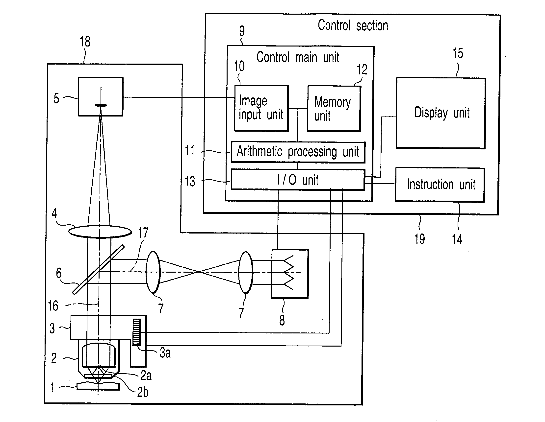
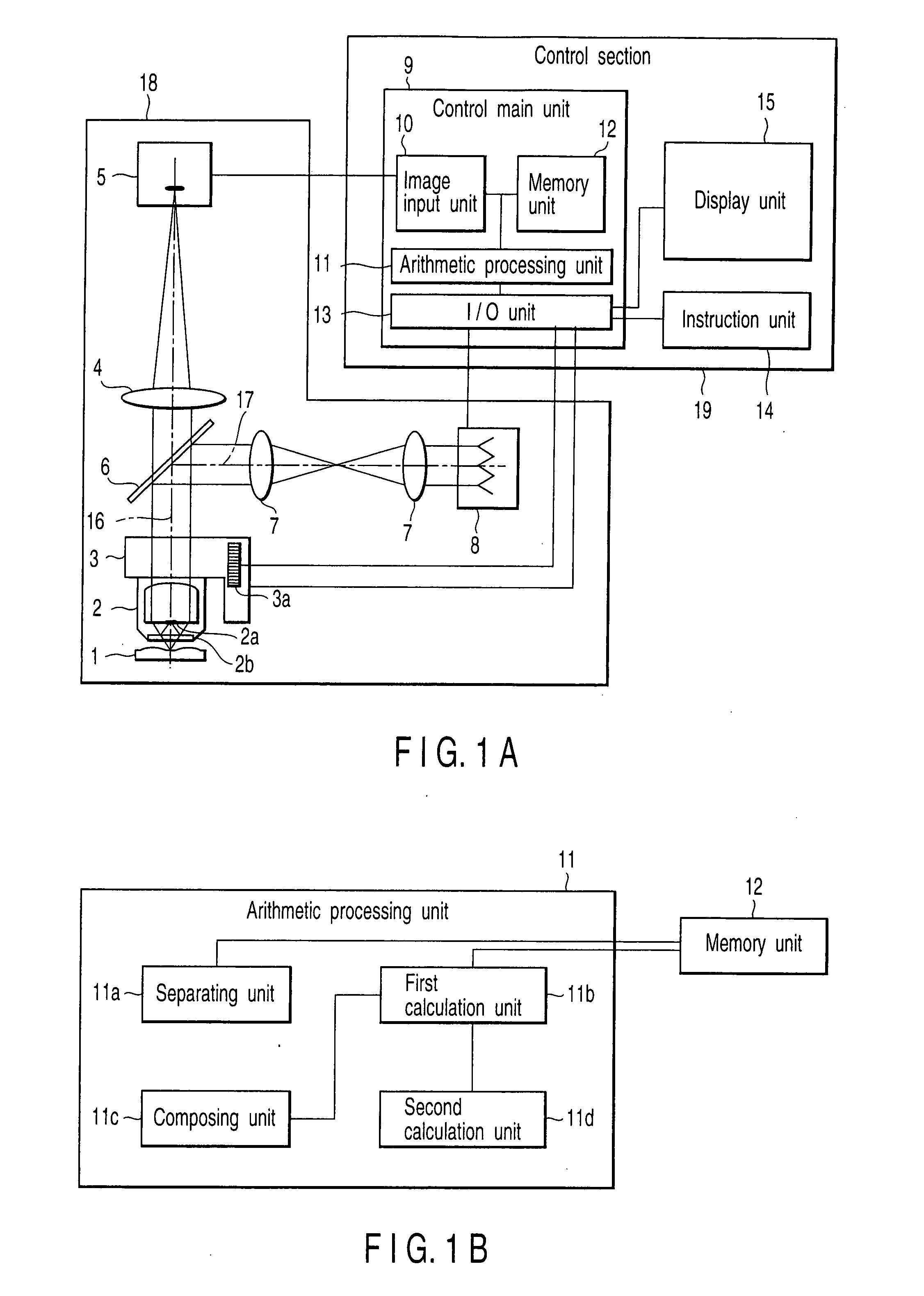
[0050]FIG. 1A is a diagram of the configuration of a three-dimensional shape measurement apparatus according to the first embodiment of the present invention. FIG. 1B is a diagram of the configuration of an arithmetic processing unit in the present embodiment. The three-dimensional shape measurement apparatus in the present embodiment roughly has a Mirau-type interference microscope section 18 and a control section 19. In addition, the present embodiment uses a Mirau-type interference optical system as an example, but the same basic configuration, operation and effects are also provided by a Michelson-type interference optical system.

[0051]In the Mirau-type interference microscope section 18, there are sequentially arranged a white light source 8 for emitting light, an illumination optical system 7 which is composed of a plurality of lenses and which tra...


PUM


Abstract

The present invention provides a three-dimensional shape measurement method and a three-dimensional shape measurement apparatus. Color luminance data I (x, y) is separated by an arithmetic processing unit into R, G and B which are color components of a color image. Then, maximum amplitude values are calculated, and the maximum values are composed to obtain an in-focus color omnifocal image. Further, a Z-position corresponding to the maximum amplitude value in an interferogram is calculated in at least one color component, and this processing is performed for all pixels (x, y) to calculate height information for a sample. The height information is provided to the color omnifocal image, such that the three-dimensional shape of the sample can be measured.

Description

CROSS-REFERENCE TO RELATED APPLICATIONS[0001]This application is based upon and claims the benefit of priority from prior Japanese Patent Application No. 2006-171782, filed Jun. 21, 2006, the entire contents of which are incorporated herein by reference.BACKGROUND OF THE INVENTION[0002]1. Field of the Invention[0003]The present invention relates to a three-dimensional shape measurement method and a three-dimensional shape measurement apparatus for acquiring height information for a sample and a color omnifocal image thereof.[0004]2. Description of the Related Art[0005]A microscope interferometer measurement method is generally known as a method of measuring the three-dimensional shape of a micro-sample with high precision. For example, in a microscope interferometer measurement method disclosed in the specification of U.S. Pat. No. 5,133,601, light having a wide wavelength band emitted from a white light source (e.g., a halogen lamp or mercury lamp) is applied to a sample by an inte...

Claims


Application Information

Patent Timeline
IPC IPC(8): G01B11/02
CPCG01B11/2441
Inventor FUJII, AKIHIRO
Owner OLYMPUS CORP
Learn More