
Mobile, retractile, lateral deploying, vehicle disablement device

a technology of vehicle disablement and retractable wheels, which is applied in the direction of roofs, roads, instruments, etc., can solve the problems of disabling the vehicle and puncting the tir

Active Publication Date: 2008-05-29
MOORMEIER MICHAEL PATRICK +2
View PDF8 Cites 23 Cited by
  • Summary
  • Abstract
  • Description
  • Claims
  • Application Information

AI Technical Summary

Benefits of technology

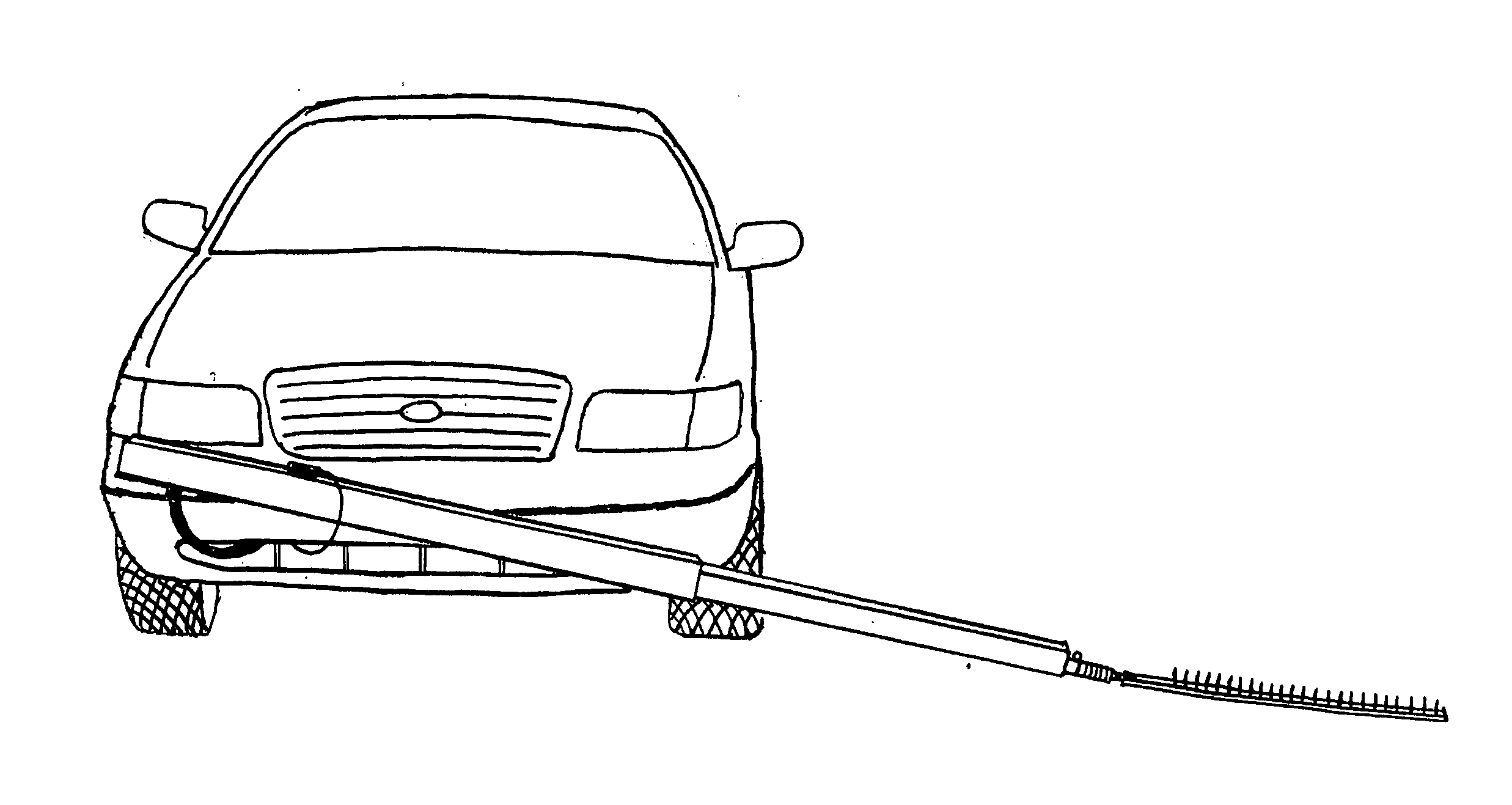
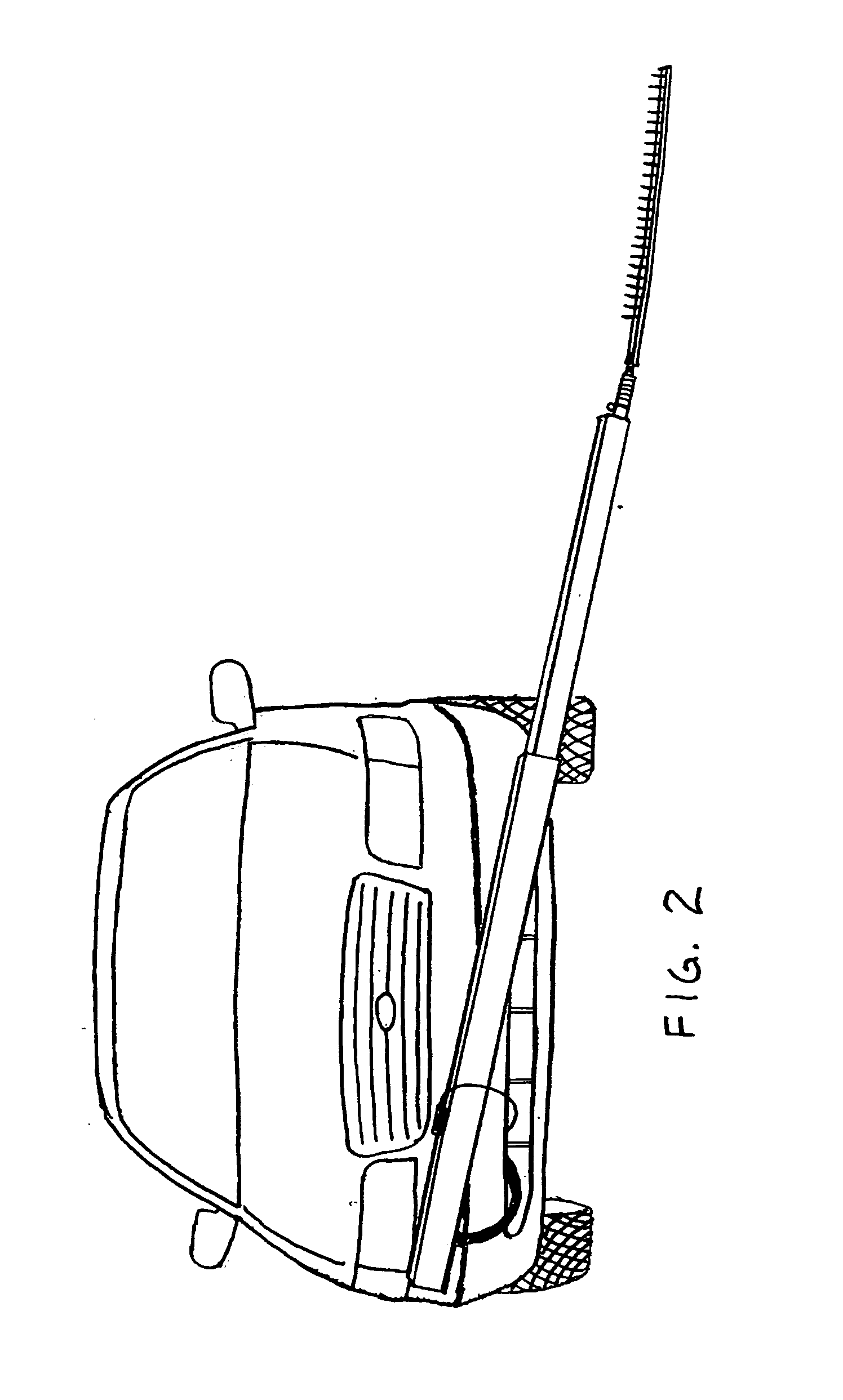
[0020]In accordance with the present invention, there is provided a device which upon activation, disables a fleeing vehicle from within the safety of the operator's vehicle. The device mounts directly to the operator's vehicle. This device is controlled by the operator from within the vehicle by way of a control panel mounted within reach of either the driver or passenger of said vehicle. When deemed necessary, the system is armed using a protected switch mounted on said panel. This sends power to the momentary deployment switch and allows for instant deployment upon activation of said momentary deployment switch. Upon positioning of operator car, the momentary deployment switch is activated, allowing air from the air reservoir to flow through the solenoid valve and air hose to pressurize the telescoping assembly and thereby extend the piston and inner tube outward to their limiting stops. This action extends the spike strip outside of the inner tube laterally at a downward angle determined by the angle which telescoping assembly is mounted to vehicle. This places the spike strip under the pursued vehicle, in front of one or more of the pursued vehicle's tires. At this point, the operator of the device needs merely to apply the brakes of said vehicle, thereby causing the spike strip to travel under the pursued vehicle's tire, puncturing said tire and disabling the vehicle. Once the spike strip has traveled under the tire of the pursued vehicle, the operator needs only to remove pressure from the momentary deployment switch, causing the solenoid valve to exhaust the pressure within the telescoping assembly, allowing the large and small constant force springs to automatically retract and safely stow itself within the outer tubing from whence it came. The system can then be re-deployed at will.

Problems solved by technology

At this point, the operator of the device needs merely to apply the brakes of said vehicle, thereby causing the spike strip to travel under the pursued vehicle's tire, puncturing said tire and disabling the vehicle.

Method used


Image

  • Mobile, retractile, lateral deploying, vehicle disablement device
  • Mobile, retractile, lateral deploying, vehicle disablement device
  • Mobile, retractile, lateral deploying, vehicle disablement device

Examples


Embodiment Construction

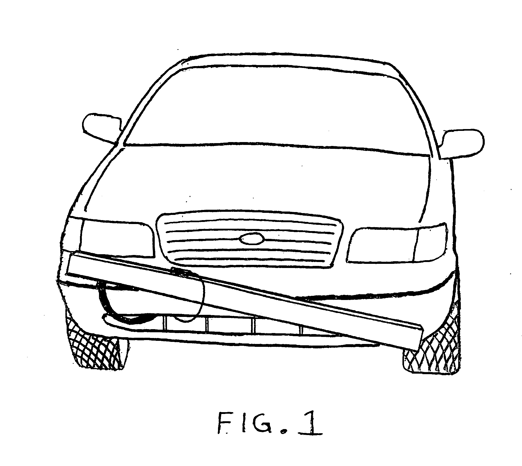
[0043]FIG. 1 is a front perspective view of a mobile, retractile, lateral deploying, vehicle disablement device, in retracted position, mounted to vehicle.

[0044]FIG. 2 is a front perspective view of a mobile, retractile, lateral deploying, vehicle disablement device, in deployed position, mounted to vehicle.

[0045]FIG. 3 is a front view of a mobile, retractile, lateral deploying, vehicle disablement device, with electrical and pneumatic systems attached. Telescoping assembly 510 may be constructed of metal, plastic, or any suitable material forming a square, rectangle or any suitable shape when viewed from either end. Telescoping assembly 510 consists of all the elements listed except for the electrical and pneumatic systems. Telescoping assembly 510 is connected to the electrical and pneumatic systems using magnetic switch cable 232 and pneumatic air hose 224.

[0046]FIG. 4 is a front view of an electrical and pneumatic systems.

[0047]Air hose 224 is a flexible, rubber-like hose or oth...


PUM


Abstract

A device when activated, disables a fleeing vehicle from within the operator's vehicle. The device mounts directly to the operator's vehicle. This device is controlled by the operator from within the vehicle by way of a control panel. When deemed necessary, the system is armed using a switch mounted on said panel. This allows for deployment upon activation of said switch. Upon positioning of operator car, the switch is activated, extending spike strip laterally. This places the spike strip under the pursued vehicle, in front of one or more of the tires. The operator applies the brakes of said vehicle, causing the spike strip to travel under the pursued vehicle's tire, disabling the vehicle. Upon traveling under the tire, the operator removes pressure from switch, causing the unit to safely stow itself. The system can then be re-deployed at will.

Description

RELATED APPLICATIONS[0001]The present application is a continuation-in-part application of U.S. provisional patent application, Ser. No. 113264, filed Dec. 1, 2005, for MOBILE, LATERAL DEPLOYING, TIRE DEFLATION DEVICE, by Michael P. Moormeier, Todd C. O'Halloran, included by reference herein and for which benefit of the priority date is hereby claimed.FIELD OF THE INVENTION[0002]The present invention relates to vehicle disablement and, more particularly, to a device that is mobile and retractile.BACKGROUND OF THE INVENTION[0003]In the year 2005, there were over 750 police pursuits in the city of Los Angeles alone. In the state of California, in that same year, there were over 7,000 police pursuits. No less than three deaths, in the city of Los Angeles alone, can be attributed to those who would run from the police, recklessly endangering the lives and property of American citizens. Unfortunately, law enforcement officials have very limited resources in dealing with this problem. Sol...

Claims


Application Information

Patent Timeline
Patent Type & Authority Applications(United States)
IPC IPC(8): E01F13/12B62D25/14F16B15/00B60R19/24B60R19/48E01H3/02
CPCE01F13/12Y10T137/6914
Inventor MOORMEIER, MICHAEL PATRICKO'HALLORAN, TODD CORY
Owner MOORMEIER MICHAEL PATRICK
Learn More