Method and device for transmission of wide-beam in an ultrasonic diagnostic system

a diagnostic system and ultrasonic technology, applied in tomography, instruments, applications, etc., can solve the problems of distorted scan lines, limited imaging rate, and limitations on 3d image speed

Active Publication Date: 2008-05-29
SHENZHEN MINDRAY BIO MEDICAL ELECTRONICS CO LTD
View PDF9 Cites 67 Cited by
  • Summary
  • Abstract
  • Description
  • Claims
  • Application Information

AI Technical Summary

Benefits of technology

[0035]The device for transmission of wide beam in ultrasonic diagnostic systems of the present invention has the advantages over the prior arts that it makes it possible for an ultrasonic system transmitting unipolar or bipolar transmit waveform to transmit a wide beam covering all receive lines, by dividing the aperture of the probe into a plurality sub-apertures and accumulation of the acoustic fields of the sub-apertures after focusing.

Problems solved by technology

The imaging rate may be limited by the relatively low frame rate, which in turn poses limitations on 3D image speed.
A main problem associated with this technique is distortion, i.e., obtained scan-lines will be distorted if the transmit beam does not cover all the scan-lines.
Therefore, an important issue concerned with multi-beam techniques is to make the transmit beam to cover a range of received scan-lines, i.e., a technique for transmission of wide beam.
The above-discussed techniques have the disadvantages that wide beam is obtained by transmitting any waveform (U.S. Pat. No. 6,585,648) or by controlling the transmit apodizing curve (U.S. Pat. No. 6,282,963).
However, the premise for implementing these methods is that a front end of an ultrasonic system can transmit arbitrary waveform, which is impossible for lots of ultrasonic systems that can transmit only excitation waveform of unipolar or bipolar levels.

Method used


Image

  • Method and device for transmission of wide-beam in an ultrasonic diagnostic system
  • Method and device for transmission of wide-beam in an ultrasonic diagnostic system
  • Method and device for transmission of wide-beam in an ultrasonic diagnostic system

Examples


Embodiment Construction

[0043]The device and method of the present invention are now discussed in detail with reference to the following embodiments and the drawings.

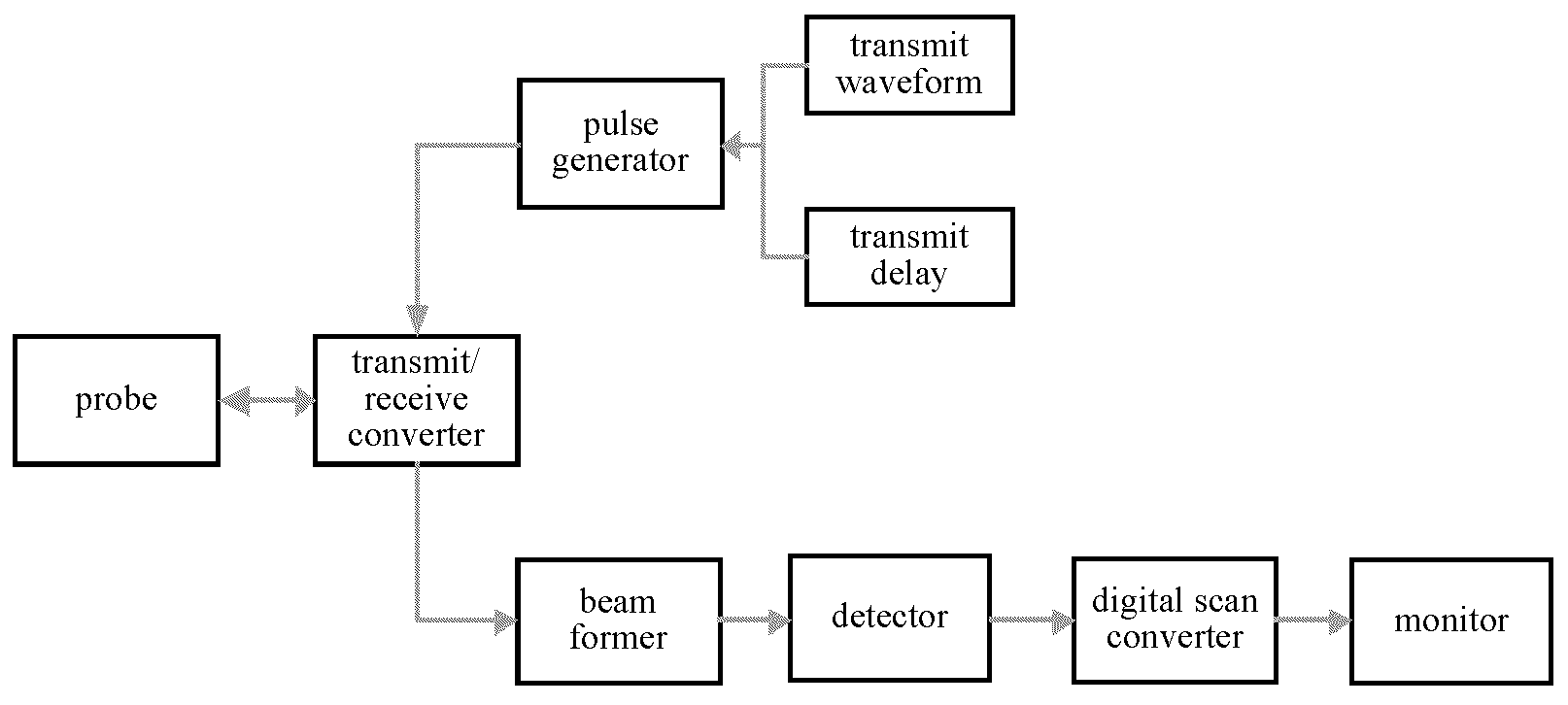
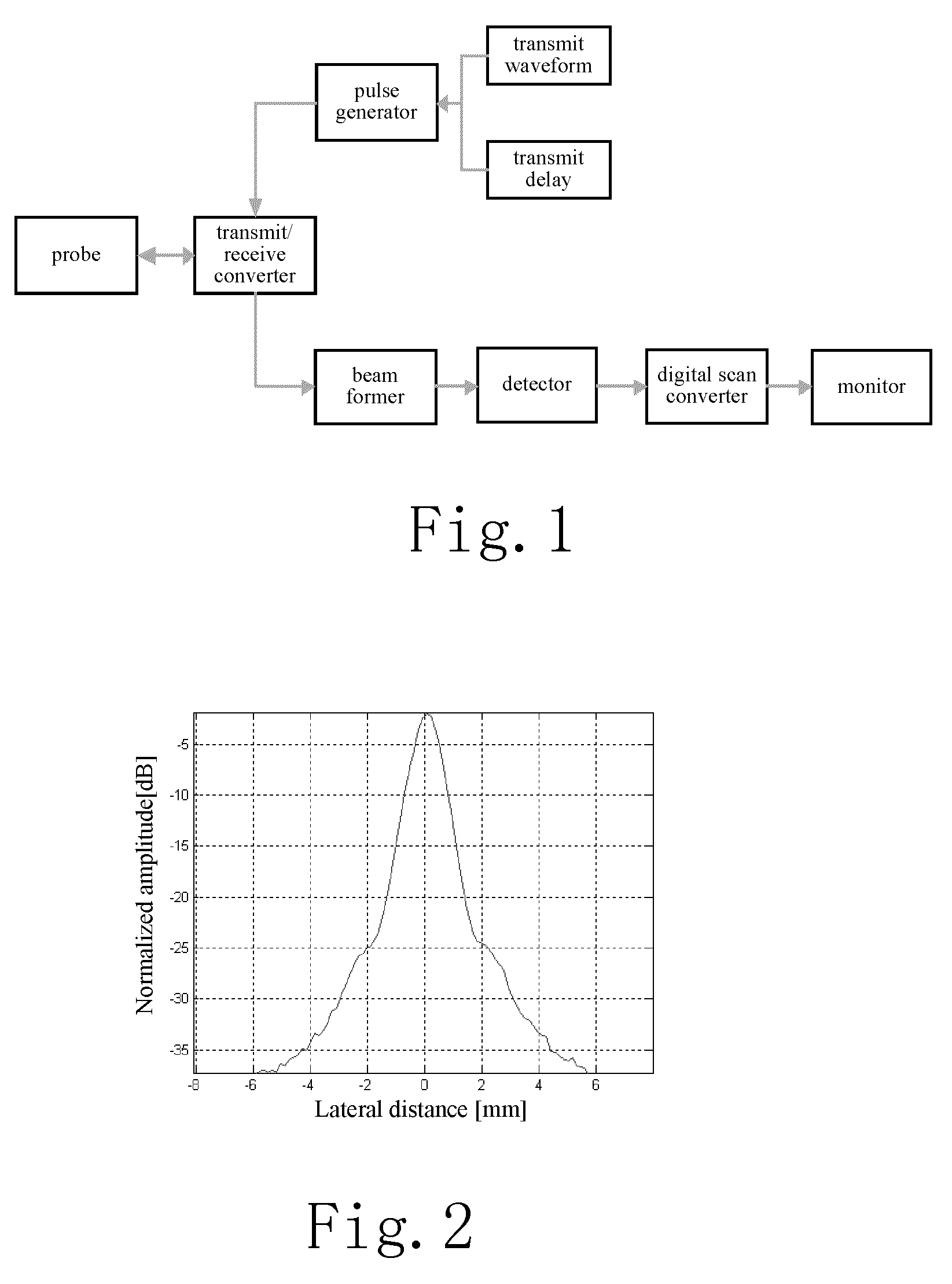
[0044]FIG. 1 shows a block diagram of a medical ultrasonic imaging system according to an embodiment of the present invention. For each channel of an ultrasonic probe, a transmit waveform and a transmit delay are set during transmission. A pulse generator converts a digital signal of the transmit waveform to an analog signal so as to excites the array elements of the probe. The array elements are excited to generate ultrasonic waves which penetrate body tissues and produces echoes. The probe enters a receiving mode after transmission. The echoes data of a plurality of channels are passed a beam former to form scan-line data. The current scan-line data is still a high frequency data which needs to be demodulated and processed by a detector. Then the data processed by a digital scan converter can be displayed on a monitor.

[0045]In the case of co...


PUM


Abstract

A method and device for transmission of wide beam in ultrasonic diagnostic systems is disclosed. The method comprises: dividing an aperture of an ultrasonic probe into N sub-apertures; laterally dividing a focus into N sub-focuses, wherein the N sub-apertures correspond to the N sub-focuses respectively, each sub-aperture has M array elements which all focus on a sub-focus corresponding to said sub-aperture; and N and M are integers larger than 2; exciting the N sub-apertures by a pulse generator, so as to obtain a laterally stretched transmit acoustic filed, wherein the transmit acoustic fields of the N sub-apertures focus on the corresponding sub-focuses respectively; and accumulating the acoustic fields of the sub-apertures to form an acoustic field of a wide beam covering acoustic fields of all receive lines. The present invention makes it possible for the system to transmit wide beams covering all receive lines, by dividing the aperture of the probe into a plurality of sub-apertures and accumulating the acoustic fields of the sub-apertures.

Description

FIELD OF THE INVENTION[0001]The present invention generally relates to imaging techniques for medical ultrasonic diagnostic systems, and in particular to a method and device for transmission of wide-beam in an ultrasonic diagnostic system.BACKGROUND OF THE INVENTION[0002]Fast imaging plays an important role in an ultrasonic diagnostic system in that it helps to provide a basis for more advanced techniques, i.e. a high data rate. With more information collected within a unit time, it becomes possible to perform finer image analysis and implement various techniques well. In particular, its advantages are as follows:[0003]1. Improvement on 3D / 4D Imaging[0004]Both 3D and 4D imaging are on the basis of processing an extremely large amount of data. The imaging rate may be limited by the relatively low frame rate, which in turn poses limitations on 3D image speed.[0005]2. Improvement on Blood Flow Imaging[0006]The frame rate and image quality of blood flow imaging both have a direct influe...

Claims


Application Information

Patent Timeline
Patent Type & Authority Applications(United States)
IPC IPC(8): A61B8/14
CPCA61B8/06A61B8/0883A61B8/145A61B8/483G01S7/5202G01S7/52095G01S15/8927G10K11/341A61B8/486
Inventor YAO, BINHU, QINJUNYANG, BO
Owner SHENZHEN MINDRAY BIO MEDICAL ELECTRONICS CO LTD
Why Eureka
Try Eureka