
Reflux control in microsurgical system

a microsurgical system and reflux control technology, applied in the field of reflux control in microsurgical systems, can solve the problems of easy clogging of the orifice of the probe with tissue, and the approach has no ability to control the reflux pressure profile,

Inactive Publication Date: 2008-05-29
ALCON INC
View PDF29 Cites 62 Cited by
  • Summary
  • Abstract
  • Description
  • Claims
  • Application Information

AI Technical Summary

Benefits of technology

[0005]The present invention provides improved apparatus and methods for controlling reflux in a microsurgical system. In one aspect of the present invention, an apparatus for controlling reflux in a microsurgical system includes a pressurized gas source, an aspiration chamber fluidly coupled to the pressurized gas source and containing a fluid disposed therein, a first valve fluidly coupled to the pressurized gas source and the aspiration chamber, a second valve fluidly coupled to the pressurized gas source and the aspiration chamber, an accumulator fluidly coupled to the pressurized gas source and the aspiration chamber between the first valve and the second valve, a pressure transducer fluidly coupled to the accumulator, and a computer electrically coupled to the first valve, the second valve, the accumulator, and the pressure transducer. The apparatus creates a reflux pressure pulse in the aspiration chamber by the computer maintaining the first valve in an o

Problems solved by technology

These probes have small orifices that are easily clogged with tissue.
This approach has no ability to control the reflux pressure profile.

Method used


Image

  • Reflux control in microsurgical system
  • Reflux control in microsurgical system

Examples


Embodiment Construction

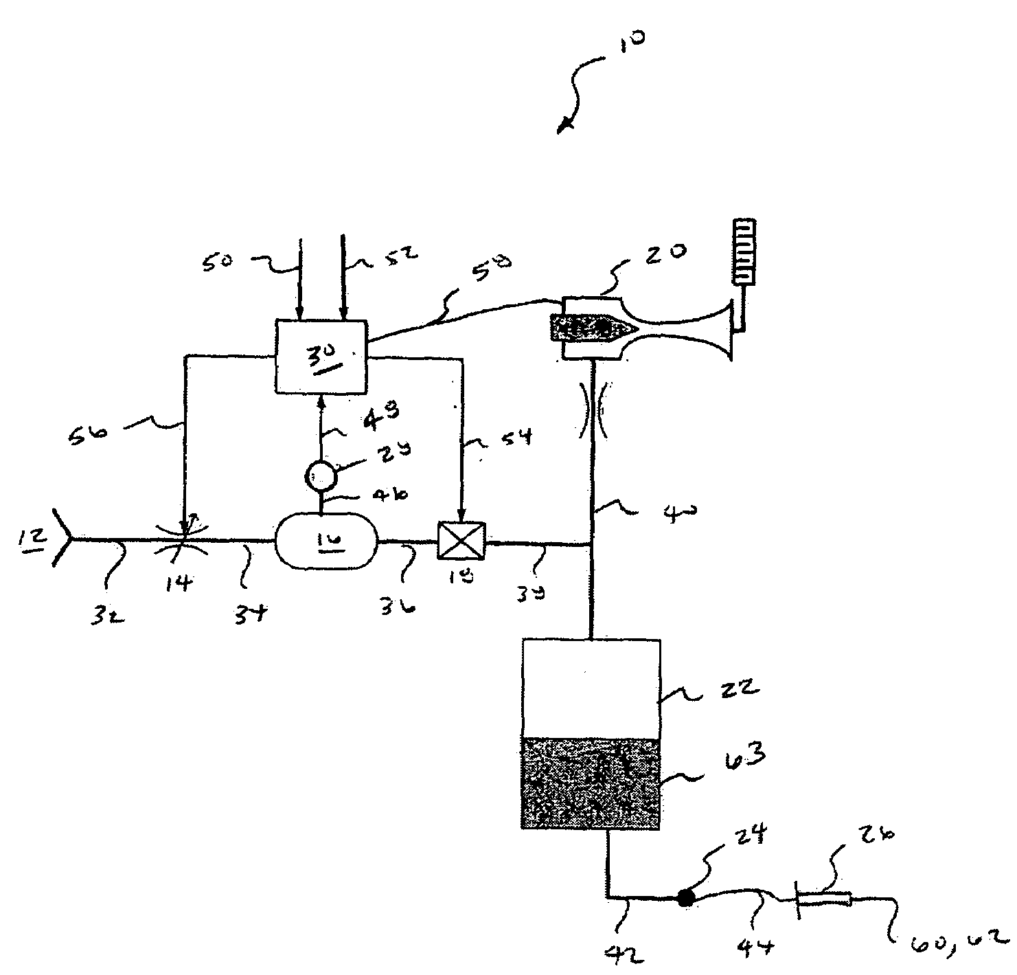
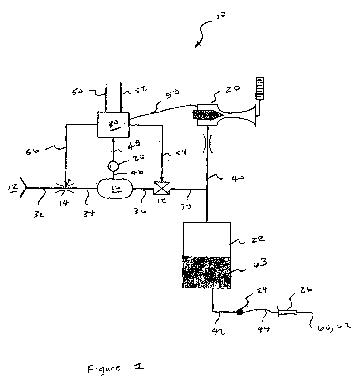
[0007]The preferred embodiment of the present invention and its advantages is best understood by referring to FIG. 1 of the drawings. Microsurgical system 10 preferably includes a pressurized gas source 12, a proportional valve 14, an accumulator 16, an isolation valve 18, a vacuum generator 20, an aspiration chamber 22, an aspiration port 24, a surgical device 26, a pressure transducer 28, and a computer or microprocessor 30. The various components of system 10 are fluidly coupled via fluid lines 32, 34, 36, 38, 40, 42, 44, and 46. The various components of system 10 are electrically coupled via interfaces 48, 50, 52, 54, 56, and 58. Valve 14 is preferably a proportional solenoid valve. Accumulator 16 preferably has a volume of about 15 cc. Valve 18 is preferably an “on / off” solenoid valve. Vacuum generator 20 may be any suitable device for generating vacuum but is preferably a vacuum chip or a venturi chip that generates vacuum. Surgical device 26 may be any surgical device that a...


PUM


Abstract

A microsurgical system capable improving reflux via programmable, pre-defined reflux profiles and a pressure accumulator.

Description

FIELD OF THE INVENTION[0001]The present invention generally pertains to controlling reflux in microsurgical systems and more particularly to controlling reflux in ophthalmic microsurgical systems.DESCRIPTION OF THE RELATED ART[0002]During small incision surgery, and particularly during ophthalmic surgery, small probes are inserted into the operative site to cut, remove, or otherwise manipulate tissue. During these surgical procedures, fluid is typically infused into the eye, and the infusion fluid and tissue are aspirated from the surgical site. These probes have small orifices that are easily clogged with tissue. Such clogging is typically referred to as “occlusion”, “tip occlusion”, or “port occlusion”. The process of clearing such occlusions is typically referred to as “reflux”.[0003]More generally, reflux is the ability to reverse the direction of the aspiration flow in a surgical system. Reflux may also be used for visualization of the surgical site (e.g. by moving blood and ot...

Claims


Application Information

Patent Timeline
IPC IPC(8): A61F9/007A61M1/00
CPCA61M1/0031A61F9/00736A61M1/804A61M1/74A61M1/00A61B17/00
Inventor HOPKINS, MARK A.GAO, SHAWN X.
Owner ALCON INC
Features
  • Generate Ideas
  • Intellectual Property
  • Life Sciences
  • Materials
  • Tech Scout
  • Unparalleled Data Quality
  • Higher Quality Content
  • 60% Fewer Hallucinations
Learn More