[0039]Referring to FIG. 9, there is shown a building panel 900 formed from a single roll of ASTM standard A-653 steel sheet metal having a thickness ranging from about 24 gauge to 16 gauge. It shall be understood that the panel 900 may be formed of numerous gauges and other materials, such as aluminum or plastic as long as the material has the desired engineering requirements and provides the necessary structural integrity. The panel 900 comprises a central portion 902, from the ends of which extend a pair of outwardly diverging inclined side wall portions 904, 906. The panel 900 also comprises two wing portions 908, 910, which extend from the outer ends of the inclined side wall portions 904, 906, respectively. It may also be preferable to include notches 912, 914 within the wing portions 908, 910 to increase the stiffness of those portions. Similarly, although they are not illustrated in FIG. 9, it may be preferable to include a notch stiffener within each of the inclined side wall portions.
[0040]Unlike the panel 400 illustrated in FIG. 4, which has a straight central portion 402, the panel of the present invention, as illustrated in FIG. 9, includes a curved central portion 902. In comparison to the straight profile of the central portion of the prior art, the curved central portion of the present invention provides the panel with greater stiffness. The increased stiffness, therefore, allows the panel to better absorb negative bending moments. Because the panel can withstand greater forces, such as weight, the design of the present invention will allow contractors to construct buildings using increased panel sizes, thereby removing some of the present design constraints.
[0041]Viewed from a perspective between the inclined side wall portions 904, 906, the curved central portion 902 has a concave shape. In other words, the central portion 902 has a curved shape similar to that of an arc, wherein an arc is a portion of a circle's entire circumference. The arc begins and ends at the points where the central portion 902 meets the inclined side wall portions 904, 906. The vertex of the arc (i.e., center of the circle) is located above the concave side of the arc and between the inclined side wall portions. Thus, the inclined side wall portions 904, 906 extend tangentially from the central portion 902.
[0042]In order to provide the panel with its maximum stiffness, it is preferable for the curved central portion 902 to have an arc with a radius ranging from 4 inches to 25 inches. It is further preferable for the curved central portion 902 to have a radius ranging from 4 inches to 12 inches, and it is even more preferable for the imaginary radius to range from 5 inches to 8 inches. Moreover, within the most preferred range, 6 inches is optimum radius for the arc.
[0043]These particular radial lengths can be correlated with angular ranges for the arc, wherein the angular range is measured between the imaginary vertices of the arc. For example, an arc with a radius ranging from 4 inches to 25 inches is preferably used with an arc ranging from 130° to 15°, respectively. Additionally, when the radius of the arc is 4 inches to 12 inches, it is preferable for the corresponding angular range to be 130° to 40°. The analogous angular ranges for a 5 inches to 8 inches arc is 120° to 60°. Furthermore, the 6 inches radius translates to an 85° arc.
[0044]Continuing to refer to FIG. 9, at the end of one wing portion 910 is a hem portion 918, and at the end of the other wing portion 908 is a complementary hook portion 916 capable of receiving the hem portion 918. Referring to FIG. 10, and particularly FIG. 10A, the hook portion 916 comprises an inclined section 934, an intermediate section 936 and a downward edge section 938. Similarly, the hem portion 918 comprises an inclined section 920 and an end section 922.
[0045]The inclined section 934 of the hook portion 916 is parallel to the inclined section 920 of the hem portion 918. The intermediate section 936 of the hook portion 916 is parallel to the end section 922 of the hem portion 918, and both the intermediate section 936 and the end section 922 are parallel to the wing portions 908, 910. Thus, when two panels 900 are adjacent one another, the hook portion 916 from one panel and the hem portion 918 of another panel matingly engage and form a connection therebetween. Accordingly, a building structure 1000 is formed and additional panels 900 can be added to the structure by connecting further panels thereto.
[0046]As mentioned above, these panels are typically manufactured at a construction site. Thus, as discussed in U.S. Pat. Nos. 5,249,445 and 5,359,871, which are both hereby incorporated by reference, a machine capable of producing the panel of the present invention is preferably mounted on a movable trailer. This provides a contractor the ability to locate the machine directly at the particular construction site where a building utilizing such panels can be erected.
[0047]The machine includes multiple components, such as a panel forming apparatus, a shear and a crimping machine, which are all placed at different locations on the trailer. It is typical for the panel forming apparatus and the shear to be placed on one side of the trailer, while the panel crimping machine is located on the other side. The components of the panel forming apparatus include a roll holder for holding a roll of sheet metal of appropriate gauge from which the building panels are formed. The panel forming apparatus also comprises a roll forming machine, which includes a plurality of metal forming rolls for forming the sheet metal into the desired configuration described above in reference to FIG. 9.
[0048]After the newly shaped metal panel exits the roll forming machine, the panel enters a hydraulically operated shear that is located at the end of the roll forming station. Upon measuring the desired length of the metal, the shear cuts the panel into appropriately sized panels. In order to provide pressurized fluid to the shear, the trailer also usually has a hydraulic pump mounted on its bed. The hydraulic pump not only supplies the shear with fluid, but it also serves as the power source for other motors within the machine. In order to be completely mobile, the hydraulic pump is preferably powered by an internal combustion engine, and preferably a diesel engine, that is mounted on the trailer.
[0049]After the panels are formed into the desired profile and sheared to an appropriate length, the panels enter a panel crimping machine, which is typically located on the trailer on the side opposite the panel forming apparatus. The panel crimping machine corrugates the panel to further increase its strength and rigidity. The panel crimping machine includes multiple sets of crimping rollers. One set of crimping rollers crimps the central portion, and other sets of crimping rollers crimp the side wall portions. The crimping rollers used to corrugate the central portion of the panel are often referred to as the main crimping rollers. Thus, as a panel enters the crimping machine, the curved central portion passes between the main set of crimping rollers.
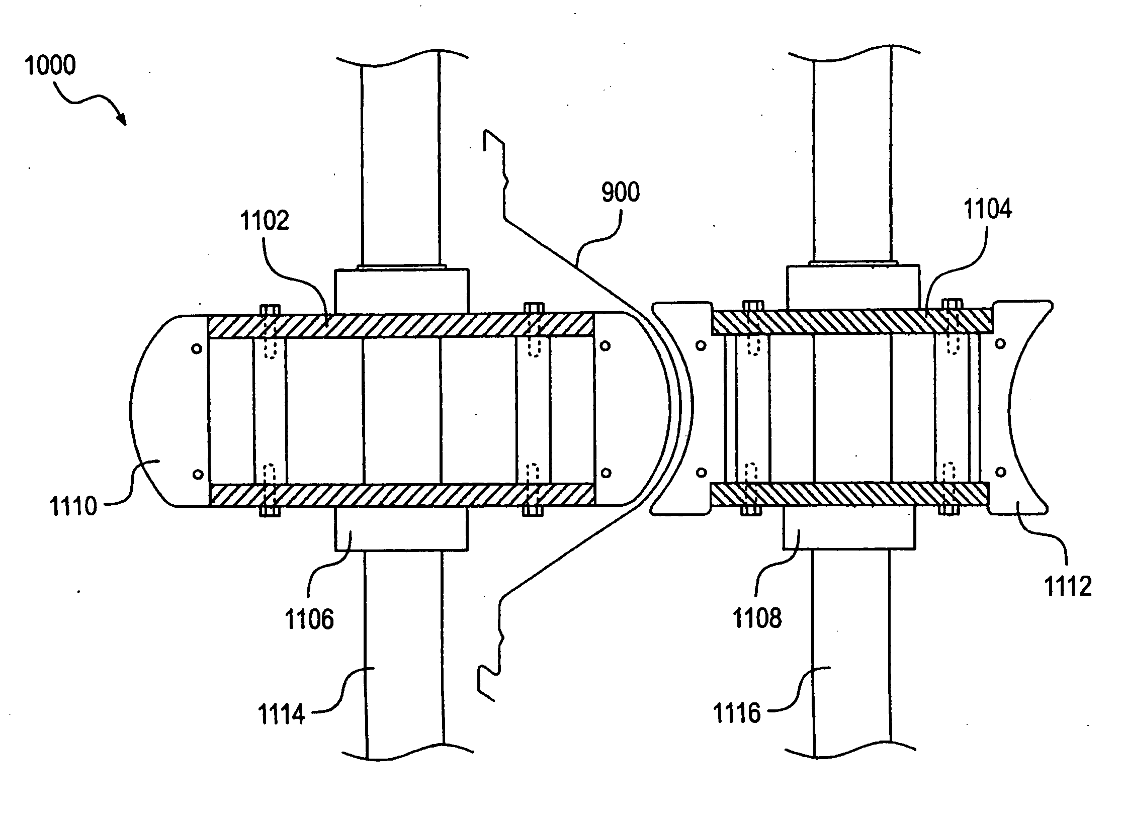
[0050]Referring to FIGS. 11 and 12, the main set of crimping rollers includes a pair of male and female crimping rollers 1102, 1104 that corrugate the central portion of the building panel 900. The crimping rollers 1102, 1104 are designed to accommodate for the profile of the curved central portion of the panel 900, thereby allowing it to pass therebetween. Specifically, both the male and female crimping rollers 1102, 1104 include a plurality of crimping blades 1110, 1112 extending radially from their respective hubs 1106, 1108. The profiles of the male crimping blades 1110 and the female crimping blades 1112 are complementary because the male crimping blades 1110 have a convex profile and the female crimping blades 1112 have a concave profile. Thus, as the panel 900 goes through the crimping machine, and particularly between the crimping rollers 1102, 1104, the crimping blades 1110, 1112 intersect one another and corrugate the central portion of the panel. Specifically, the convex profiled male crimping blades 1110 contact the concave side of the central portion 902 of the panel 900, and the concave profiled female crimping blades 1112 contact the convex side of the panel.
[0051]As the panel 900 passes between the crimping rollers 1102, 1104, the crimping rollers may also create the curved profile to the central portion. In other words, as the panel leaves the panel forming machine, described above, the central portion of the panel may have a straight profile. In that case, the straight central portion would be fed into the crimping rollers, and the crimping machine would simultaneously impart the curved profile to the central portion and crimp that portion. Thus, as the panel exits the crimping machine, it would have a curved central portion with corrugations formed therein.
[0052]Each crimping roller 1102, 1104 is attached to a respective shaft 1114, 1116, and the shafts are connected to a means for driving the crimping rollers. As discussed in U.S. Pat. Nos. 4,364,253, 4,505,143 and 4,505,084, all of which are hereby incorporated by reference, there are numerous types of drive systems available for driving the crimping rollers. The drive system can be configured such that one of the crimping rollers is driven while the other idles, but it is preferable that both crimping rollers be driven.
[0053]The crimping rollers are typically driven by a motor, and because the panel forming machine and/or shear are powered by a common hydraulic system, it is preferable that the crimping machine motor also by a hydraulic motor. As mentioned above, the crimping rollers 1102, 1104 are connected to shafts 1114, 1116. Thus, the mechanical drive system links the shafts to the motor. The mechanical drive system can include a combination of shafts, gears, sprockets, pulleys, chains, belts, etc. For example, one drive system may include mounting a gear on the shaft 1114 extending through the male crimping roller 1102 and mounting another gear on the shaft 1116 extending through the female crimping roller 1104 such that both gear engage one another. That drive system shall also include an idler sprocket that engages one of the gears connected to the shafts, wherein the shaft of the motor connected is connected to and driving said idler gear, which in turn rotates the gears, thereby turning the male and female crimping rollers.
[0054]It may also be preferable to include a clutch, and particularly a reversing clutch, between the motor and the idler worm gear for maintaining a constant speed between the male and female crimping rollers. Additionally, it may also be preferable to adjust the gap between the two crimping roller 1102, 1104. If so, it would be desirable to include a gap adjusting mechanism to the crimping machine.
[0055]Although the invention has been described and illustrated with respect to the exemplary embodiments thereof, it should be understood by those skilled in the art that the foregoing and various other changes, omissions and additions may be made without departing from the spirit and scope of the invention. For example, in lieu of driving the crimping rollers in the manner described above, it may also be desirable to directly couple the motor shaft to one of the gears. Thus, other known drive systems capable of driving the complementary concave and convex crimping rollers shall be considered within the scope of this invention.