
Limb Mounting System

Active Publication Date: 2008-06-05
MCP IP
View PDF6 Cites 51 Cited by
  • Summary
  • Abstract
  • Description
  • Claims
  • Application Information

AI Technical Summary

Benefits of technology

[0015]The bow limb positive positioning system of the invention connects a bow limb to a handle riser while allowing the forward most butt of the bow limb to flex and follow the natural outward flexing of the middle portion of the bow limb between such pivot point and the limb bolt during drawing of the bow when the bow is drawn. The positive mounting system comprises complementary limb bolt head, swivel washer and limb cap that allow the butt of the bow limb to swivel during the drawing of the bow to allow the butt to follow the natural outward flexing of the middle portion of the bow limb between such pivot point and the limb bolt during drawing of the bow, thereby reducing the stress that would otherwise be imparted to the butt during drawing of the bow.
[0016]The bow limb fulcrum system of the invention is positioned at the rearward edge of the handle riser to reduce the stress imparted to a bow limb that pivots against the rearward edge of the handle riser during drawing of the bow.
[0017]The functionality of the bow limb positive positioning system and the bow limb fulcrum system of the limb mounting system of the invention work alone and in unison to significantly reduce the stresses that are imparted to the forward portion of the bow limb when the bow is at rest (when undrawn) as well as when drawn.

Problems solved by technology

Unfortunately, the pivoting of the limb against the rearward edge of the limb pocket during drawing of the bow, imparts great stress to the bow limb at the pivot point.
Premature failure of the bow limb therefore often occurs at such pivot point.

Method used


Image

  • Limb Mounting System
  • Limb Mounting System
  • Limb Mounting System

Examples


Embodiment Construction

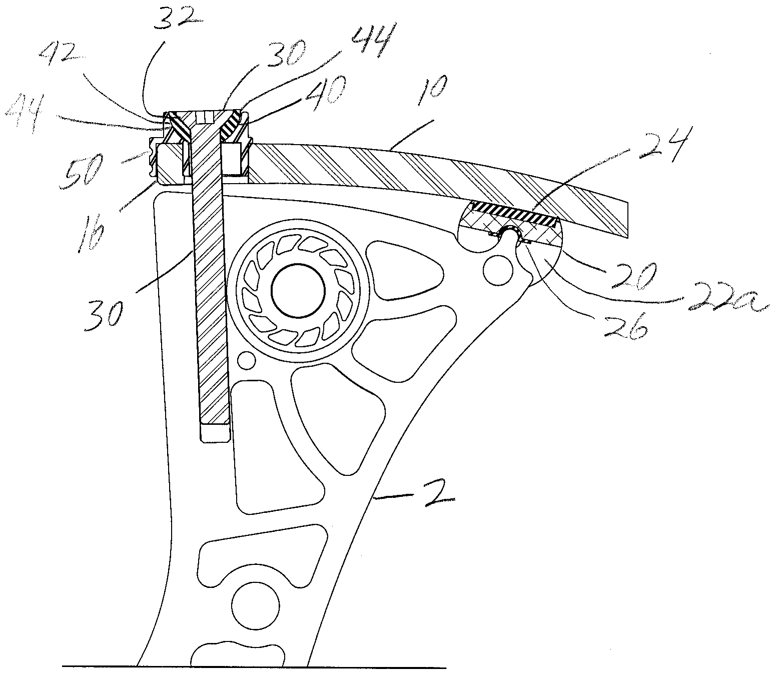
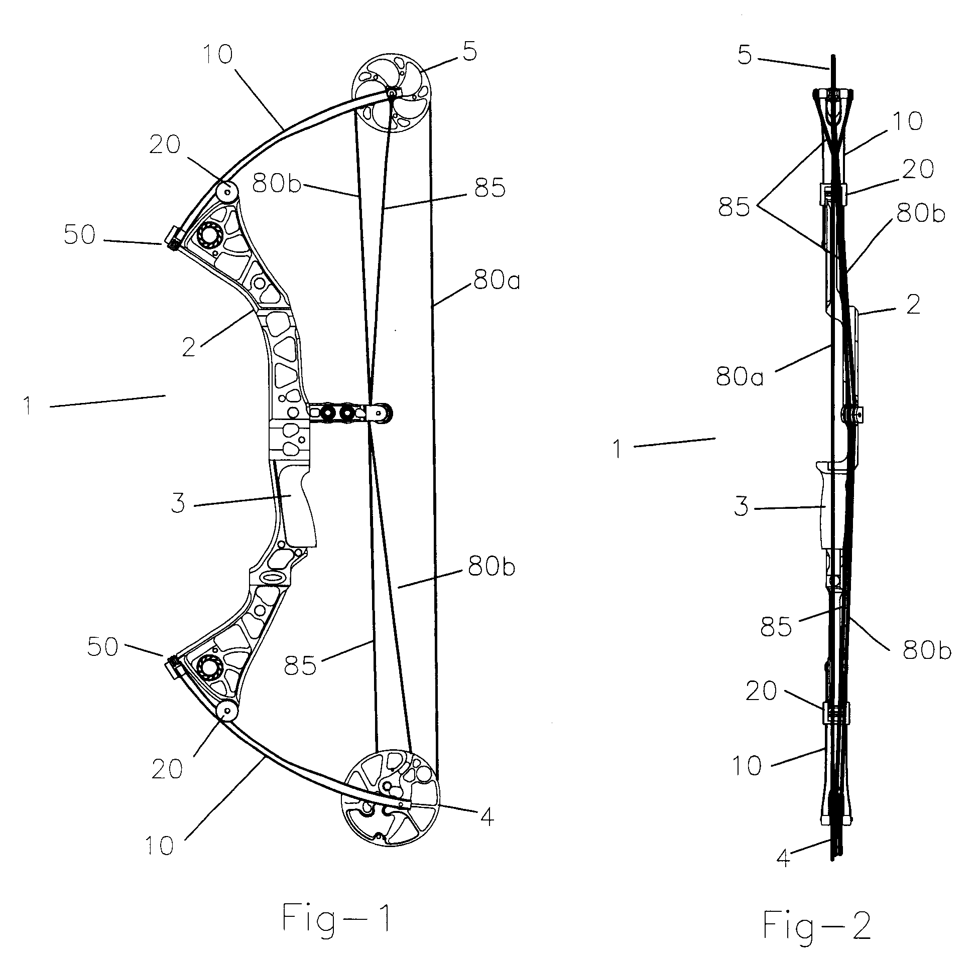
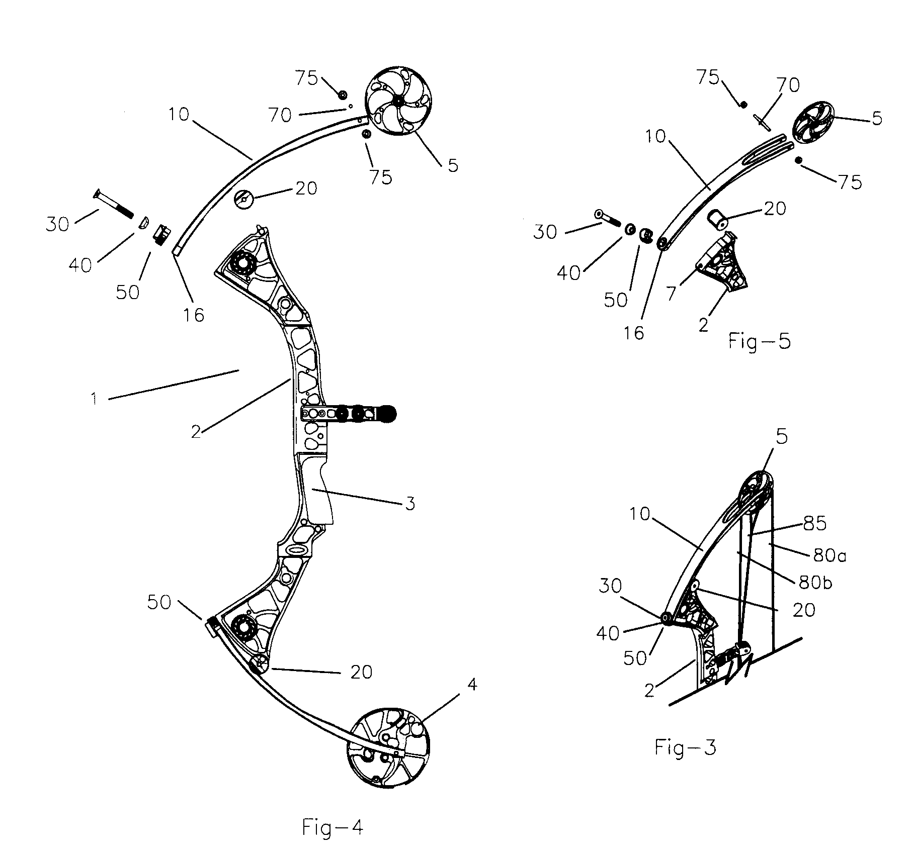
[0032]FIG. 1 shows the general configuration of a compound bow 1 with the handle / riser 2 and grip 3. The handle / riser 2 is connected to the bow limbs 10 by the limb mounting system of the invention including a limb cap 50 and a limb fulcrum 20. At the outer end of the limbs 10 is the compounding system comprising a dual feed out single take up cam 4 mounted on the bottom limb 10 and the idler wheel 5 on the top limb 10. These two components are interconnected by the harness system comprising the bowstring 80a and secondary payout 80b and the power cable 85. Without departing from the spirit and scope of this invention, the present invention may be applied to other bow configurations such as dual cam bows, cam and a half bows etc.

[0033]The bow limb positive positioning system of the bow limb mounting system of the present invention, as shown in general in FIG. 4 and FIG. 5, comprises a limb bolt 30 positioned in a snug fit into a swivel washer 40 which in turn spherically fit into th...


PUM


Abstract

An apparatus and method for reducing stress in a bow limb of an archery bow connected to a handle / riser of the bow by allowing a butt end of the bow limb connected to a forward end of the handle / riser by a limb bolt to flex forwardly when the bow is drawn and / or allowing the bow to flex rearwardly at the rearward end of the handle / riser when the bow is drawn.

Description

CROSS-REFERENCE TO RELATED INVENTIONS[0001]This application claims the benefit of provisional application No. 60 / 859,395, filed Nov. 16, 2006, the disclosure of which is hereby incorporated by reference herein.BACKGROUND OF THE INVENTION[0002]1. Field of the Invention[0003]This invention relates to archery bows. More particularly, this invention relates to an apparatus and method for mounting a bow limb to the riser of a bow handle.[0004]2. Description of the Background Art[0005]Presently there exist many different ways for mounting the upper and lower bow limbs of a compound bow to the upper and lower ends of a riser of the bow handle. Most commonly, the butt of each bow limb is positioned into a rectilinear limb pocket aligned contiguous with the outer planar surface of the bow handle riser. The butt of the limb is then affixed to the riser by a limb bolt inserted through a hole in the butt of the bow limb, through a corresponding hole in the limb pocket and then threaded into a t...

Claims


Application Information

Patent Timeline
IPC IPC(8): F41B5/14F41B5/10
CPCF41B5/10
Inventor MCPHERSON, MATHEW A.
Owner MCP IP
Features
  • Generate Ideas
  • Intellectual Property
  • Life Sciences
  • Materials
  • Tech Scout
  • Unparalleled Data Quality
  • Higher Quality Content
  • 60% Fewer Hallucinations
Learn More