[0006]In view of the above, it is an object of the invention to provide a tire mounting apparatus that is improved in such a manner that vehicle tires spanning a
large range of different inner diameters and different profile ratios can be mounted surely, reliably and without problems onto wheel rims of corresponding sizes, without requiring manual adjustment processes. The invention further aims to avoid or overcome the disadvantages of the prior art, and to achieve additional advantages, as apparent from the present specification. The attainment of these objects is, however, not a required limitation of the claimed invention.
[0008]The invention has the
advantage that the adjusting arrangement is able to achieve a radial sliding displacement and adjustment of all mounting tools while maintaining a proper angular or tangential positioning of the tools relative to the tire, for nearly all possible tire sizes. Namely, the tire mounting
machine can
mount tires of nearly all existing passenger vehicle tire sizes onto nearly all associated wheel rim sizes and types with a
diameter ranging from 12 inches to 25 inches, without requiring manual adjustment, rearrangement, or re-equipping of the mounting tools or other components of the apparatus, so that the tires of different sizes or types can be mounted successively one after another in a
fully automated manner. In that regard, the exact radial adjustment of the tire mounting tools with further consideration of maintaining the prescribed tangential angle of the mounting tools simultaneously has the
advantage that all tire types including those with extreme low profile ratios down to 25% can be mounted without problems.
[0009]Furthermore, the mechanical adjusting devices are preferably arranged within the rotatable tire mounting head. This achieves the
advantage that no rotatable electrical cable connections for adjustment motors and no rotatable pressure line connections for hydraulic oil or pneumatic
compressed air drives are necessary. Avoiding such rotatable connections is advantageous, because such connections tend to be prone to trouble and failure due to the continuous rotational motion of the mounting head while carrying out the tire mounting operation.
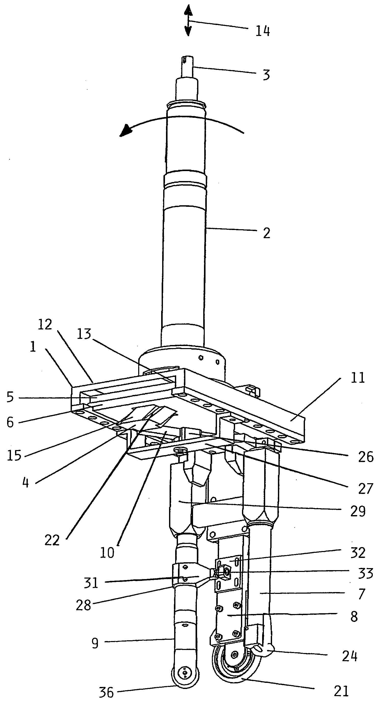
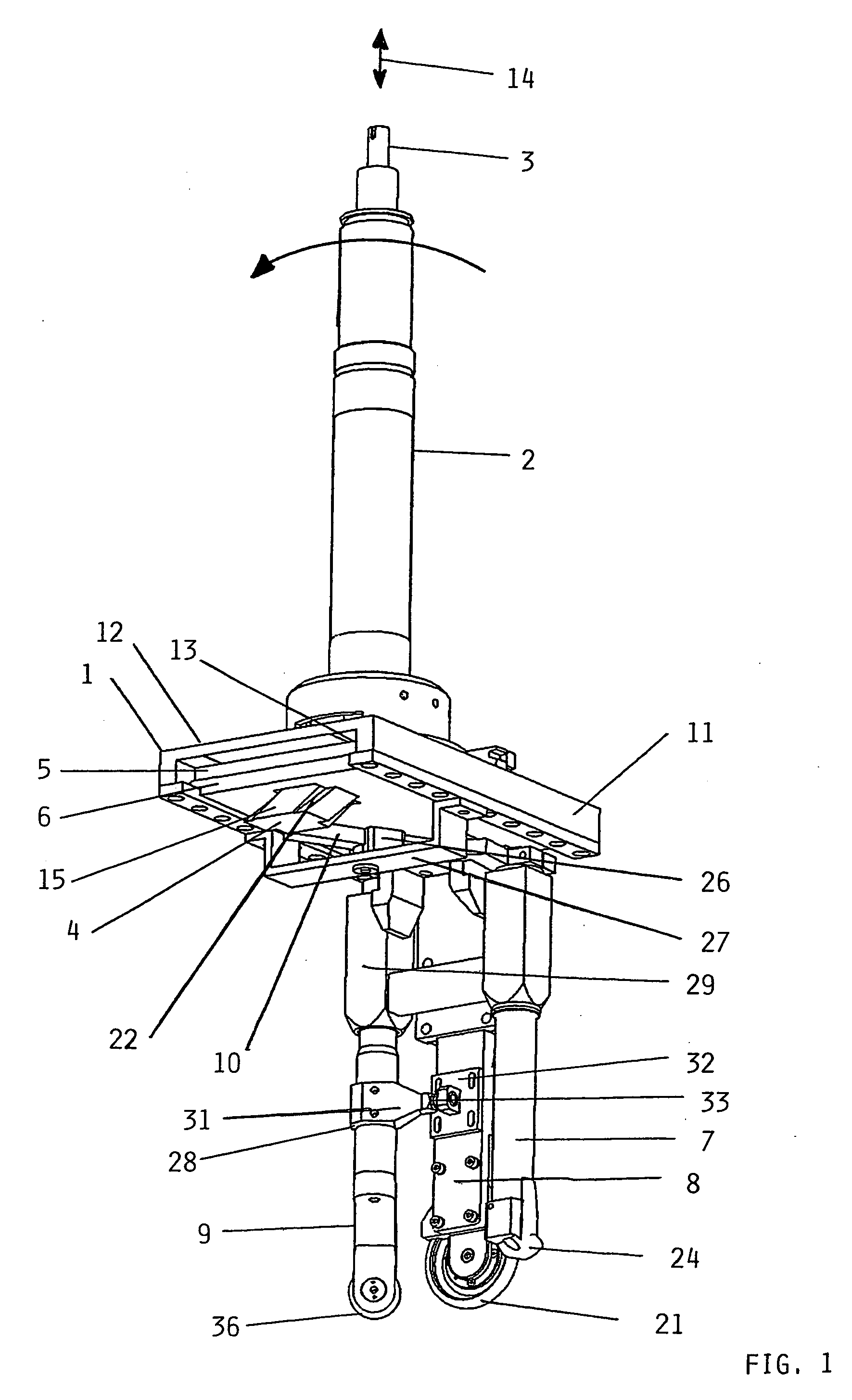
[0010]In a particular example embodiment of the inventive apparatus, the adjusting arrangement includes a push rod or thrust rod guidedly arranged axially through the
drive shaft, and the adjusting devices are driven for adjustment by the push rod. This embodiment has the advantage that with a simple
vertical motion of the push rod, which is independent of and unaffected by the rotation of the tire mounting head, it is possible to radially and tangentially adjust, independently of one another, at least two different tire mounting tools having different angular positions.
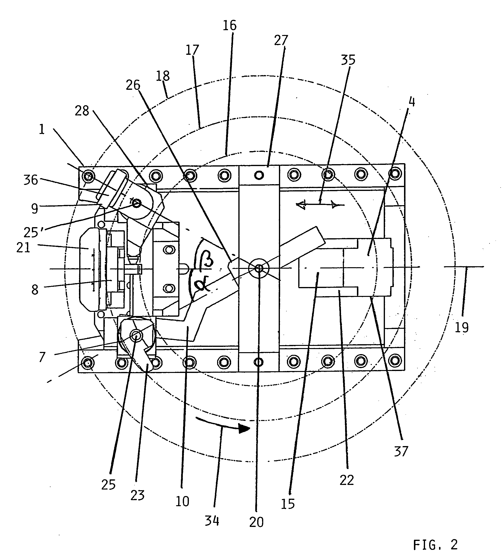
[0011]A further particular example embodiment of the inventive apparatus involves an adjusting arrangement comprising adjusting plates that are slidingly displaceable separately and differently relative to one another. A deflecting or redirecting element preferably embodied as a deflecting rod is connected to the vertical or axial push rod, so as to redirect and deflect the vertical actuation motion of the push rod into a horizontal sliding displacement motion of the adjusting plates. This has the advantage that thereby a longitudinal sliding displacement of the adjusting plates can serve to radially slidingly adjust two or three tire mounting tools with proper tangential angles thereof through radial sliding adjustment motions, so as to adjust and fit the mounting tools to a
large range of different wheel rim or disc diameters. Further preferably, the deflecting rod is configured with at least two differently sloping actuating surfaces having two different slope angles that respectively individually act on and actuate the two separate slidable adjusting plates. Thus, the two differently sloping actuating surfaces cause two different sliding displacements of the two separate slidable adjusting plates in the horizontal radial direction. As a result, the respective tire mounting tools carried by or connected to these adjusting plates simultaneously are separately adjusted as necessary in an advantageous manner to always match the
diameter of the tire being mounted.
[0012]In a further example embodiment of the inventive apparatus, the adjusting arrangement further comprises tangential adjusting devices so that the tangential angular position of each tire mounting tool is also appropriately adjusted to maintain prescribed tangential angular positions of the tire mounting tools automatically following the radial adjustment thereof, to match various different wheel rim diameters. A jointed lever or toggle lever as a tangential adjusting device slides through the rotation axis along with the longitudinal sliding displacement of a tire mounting tool (e.g. the bead deflector) to which the lever is secured, so that at least the bead deflector always remains tangentially oriented relative to the tire sidewall bead or edge. If the apparatus further includes a following roller as another tire mounting tool, the following roller is advantageously connected via a
pivot joint with the pressing roller, such that the following roller is also guided rotationally or pivotally to remain properly tangentially oriented by this tangential adjusting arrangement.

