
Enhanced vent for outlet for a cooling system

Active Publication Date: 2008-06-05
APPLE INC
View PDF21 Cites 8 Cited by
  • Summary
  • Abstract
  • Description
  • Claims
  • Application Information

AI Technical Summary

Benefits of technology

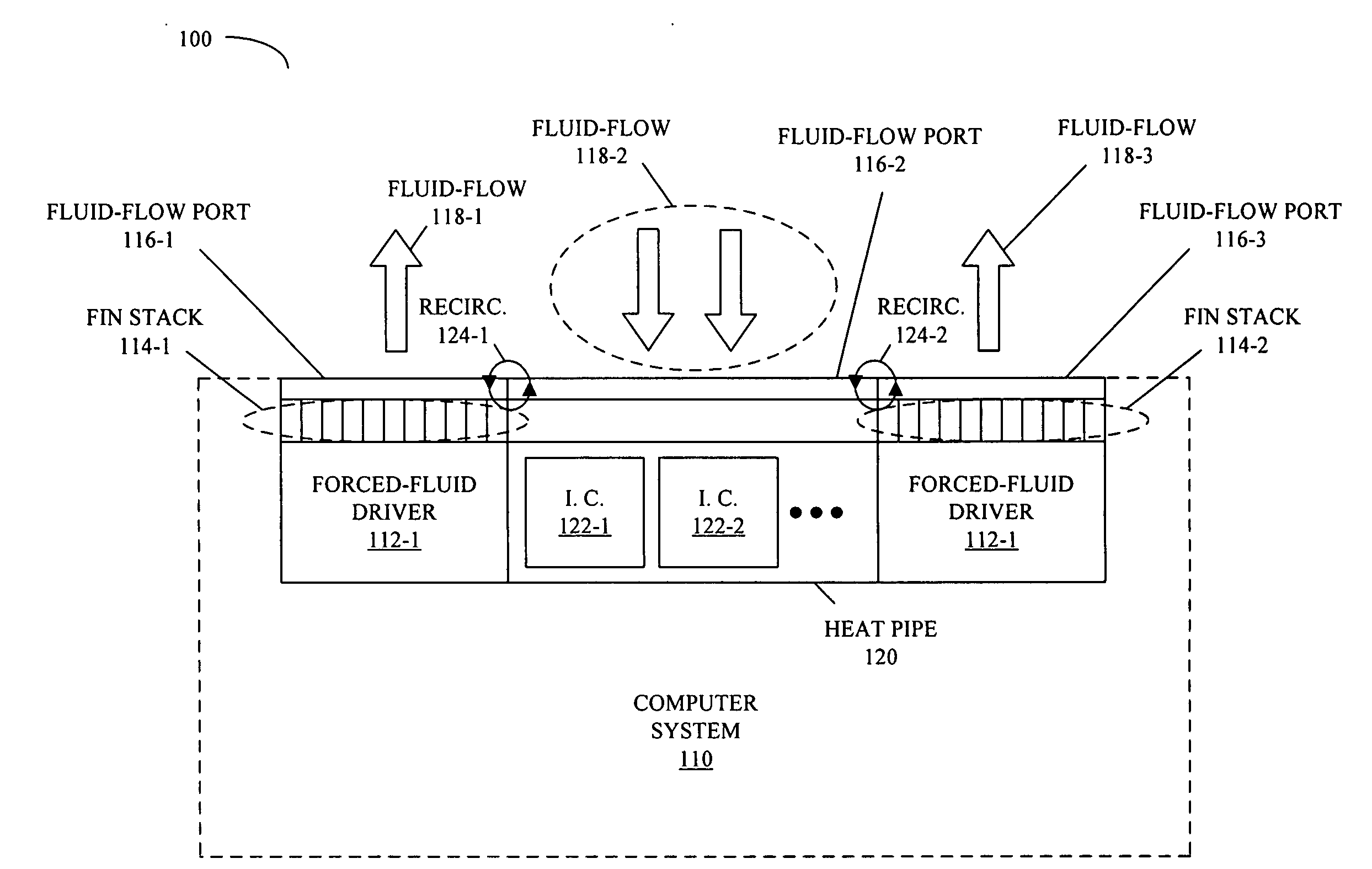
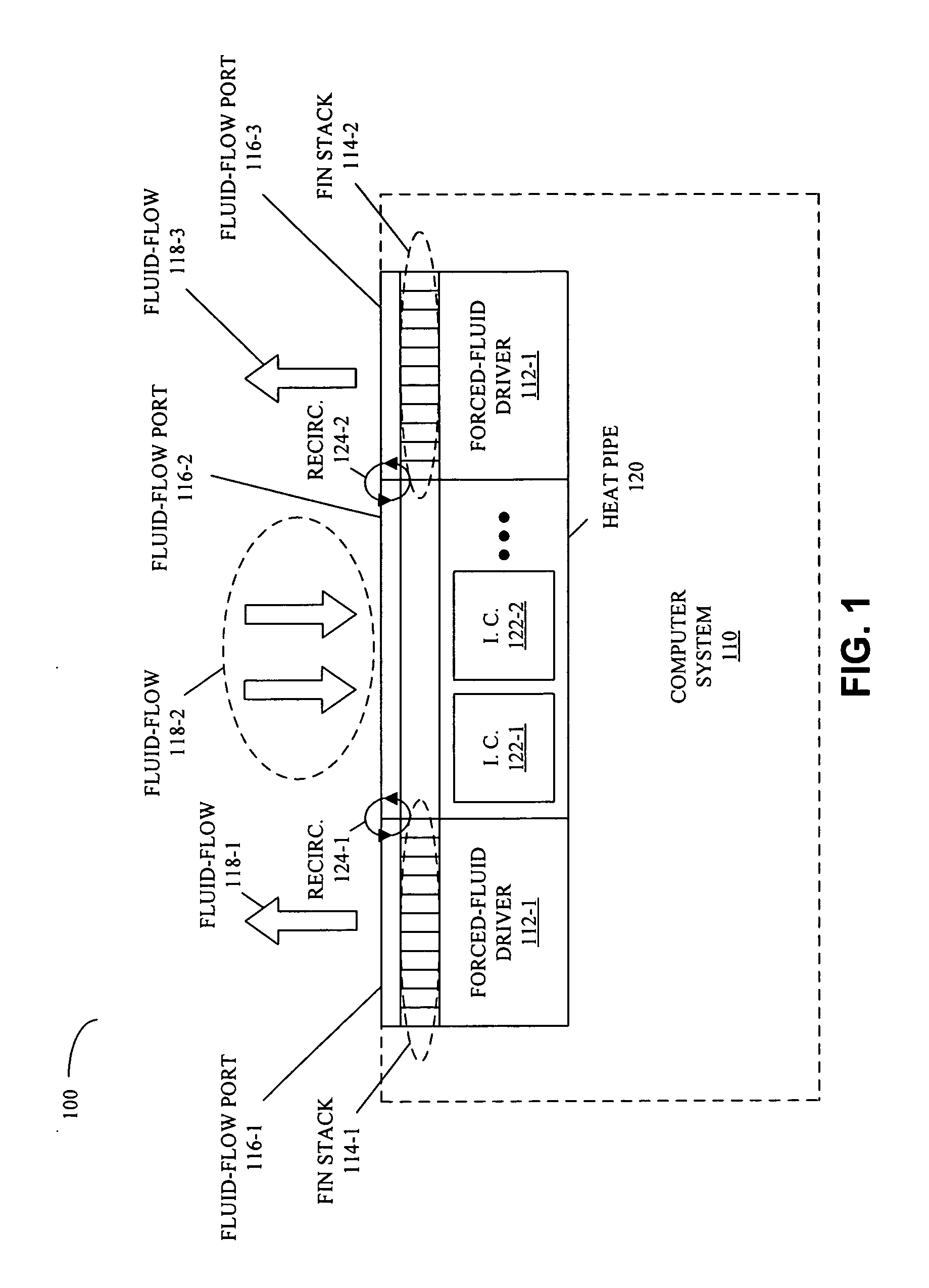
[0011]In some embodiments, the tapering of the given fluid-flow port increases the velocity and lowers the pressure of the associated fluid flow at the edge of the given fluid-flow port that is proximate to the outside of the enclosed area. In particular, the tapering of the first fluid-flow port and / or the second fluid-flow port may create a Bernoulli pump. Such a Bernoulli pump may augment the pumping of heat by the forced-fluid driver.
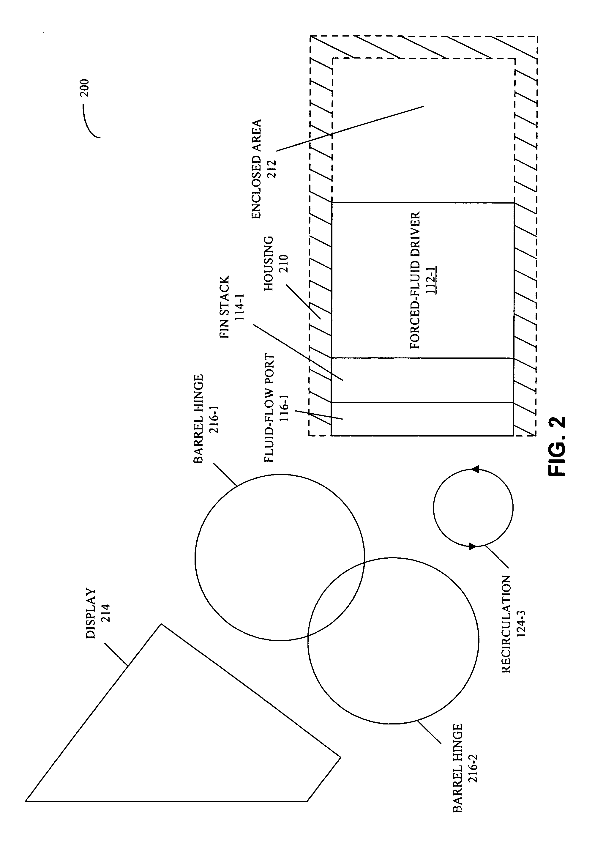
[0012]In some embodiments, the tapering of the first fluid-flow port, the second fluid-flow port, and / or the third fluid-flow port reduces recirculation of heated fluid in the enclosed area. Note that this recirculation may be associated with a hinge mechanism that partially obstructs at least one of the fluid-flow ports. For example, the hinge may be coupled to a display.

Problems solved by technology

This has caused an increase in power consumption and associated heat generation in these devices.
Consequently, it has become a considerable challenge to manage this ‘thermal load’ to maintain acceptable internal and external operational temperatures.
Portable devices, such as laptop computers (notebook PCs), cellular telephones, and personal digital assistants pose additional design constraints.
In particular, size and weight limitations in such devices can make it difficult to achieve desired operational temperatures.
Unfortunately, space restrictions often lead to partial blockages of the output vents of these fans.
This results in increased backpressure, which diverts heated air to the bottom surface and the air input vents of the laptop computer.
As a consequence, the bottom surface overheats, which is unpopular with consumers.
In addition, heated air re-circulates into the input vents of the laptop computer, thereby reducing the efficiency of the cooling system and increasing the internal temperature.

Method used


Image

  • Enhanced vent for outlet for a cooling system
  • Enhanced vent for outlet for a cooling system
  • Enhanced vent for outlet for a cooling system

Examples


Embodiment Construction

[0024]The following description is presented to enable any person skilled in the art to make and use the invention, and is provided in the context of a particular application and its requirements. Various modifications to the disclosed embodiments will be readily apparent to those skilled in the art, and the general principles defined herein may be applied to other embodiments and applications without departing from the spirit and scope of the present invention. Thus, the present invention is not intended to be limited to the embodiments shown, but is to be accorded the widest scope consistent with the principles and features disclosed herein.

[0025]Embodiments of a cooling mechanism, a computer system (such as a desktop computer and / or a laptop computer) that includes the cooling mechanism, and a method for cooling an enclosed area are described. Note that the computer system may include stationary and / or portable electronic devices, such as cellular telephones, personal digital ass...


PUM


Abstract

A cooling mechanism includes a first heat exchanger, a first fluid-flow port, and a second fluid-flow port. The first heat exchanger includes a forced-fluid driver and is configured to pump heat from inside an enclosed area to outside of the enclosed area. Furthermore, the first fluid-flow port is configured to accommodate a first fluid flow into the enclosed area and the second fluid-flow port is configured to accommodate a second fluid flow from the enclosed area. Note that the first fluid-flow port and the second fluid-flow port are approximately coplanar. In addition, a given fluid-flow port, which may be either or both of the fluid-flow ports, is tapered to have an associated cross-sectional area which is smaller at an edge of the given fluid-flow port that is proximate to the outside of the enclosed area than at an edge of the given fluid-flow port that is proximate to the inside of the enclosed area.

Description

BACKGROUND[0001]1. Field of the Invention[0002]The present invention relates to heat-transfer techniques. More specifically, the present invention relates to fluid-flow ports that reduce recirculation of heated air in computer systems.[0003]2. Related Art[0004]The computational performance provided by electronic devices has increased significantly in recent years. This has caused an increase in power consumption and associated heat generation in these devices. Consequently, it has become a considerable challenge to manage this ‘thermal load’ to maintain acceptable internal and external operational temperatures.[0005]Portable devices, such as laptop computers (notebook PCs), cellular telephones, and personal digital assistants pose additional design constraints. In particular, size and weight limitations in such devices can make it difficult to achieve desired operational temperatures. For example, many laptop computers utilize cooling systems that include fans to pump heat out of th...

Claims


Application Information

Patent Timeline
IPC IPC(8): H05K7/20
CPCG06F1/203
Inventor ALI, IHAB A.NIGEN, JAY S.
Owner APPLE INC
Learn More