Hybrid electrical switching device

a switching device and hybrid technology, applied in the direction of relays, contact mechanisms, boards/switchyards circuit arrangements, etc., to achieve the effect of simple control circuit and inherent protection

Inactive Publication Date: 2008-06-05
EATON ELECTRIC INC
View PDF13 Cites 22 Cited by
  • Summary
  • Abstract
  • Description
  • Claims
  • Application Information

AI Technical Summary

Benefits of technology

[0015]It is therefore an object of the invention to provide a hybrid switching device which is suitable for switching power consumers in electrical low-voltage supply networks with an inherent protection against damage to the semiconductor switching element in the case of a non-functioning or poorly conducting mechanical switching element and with a relatively simple control circuit built up of a small number of components.

Problems solved by technology

Consequently, the main semiconductor switching element is only loaded for half a period of the AC voltage, as a result of which insufficient heat to cause damage to the main semiconductor switching element can be developed therein.

Method used


Image

  • Hybrid electrical switching device
  • Hybrid electrical switching device
  • Hybrid electrical switching device

Examples


Embodiment Construction

[0044]Although the invention is illustrated by means of a preferred embodiment hereinafter, it should be understood that additions and alterations thereto are possible without departing from the inventive principle underlying the present invention.

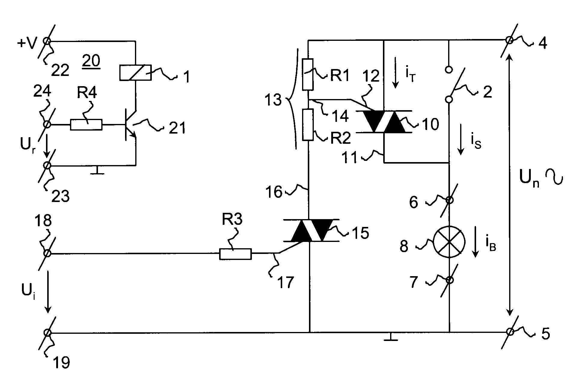
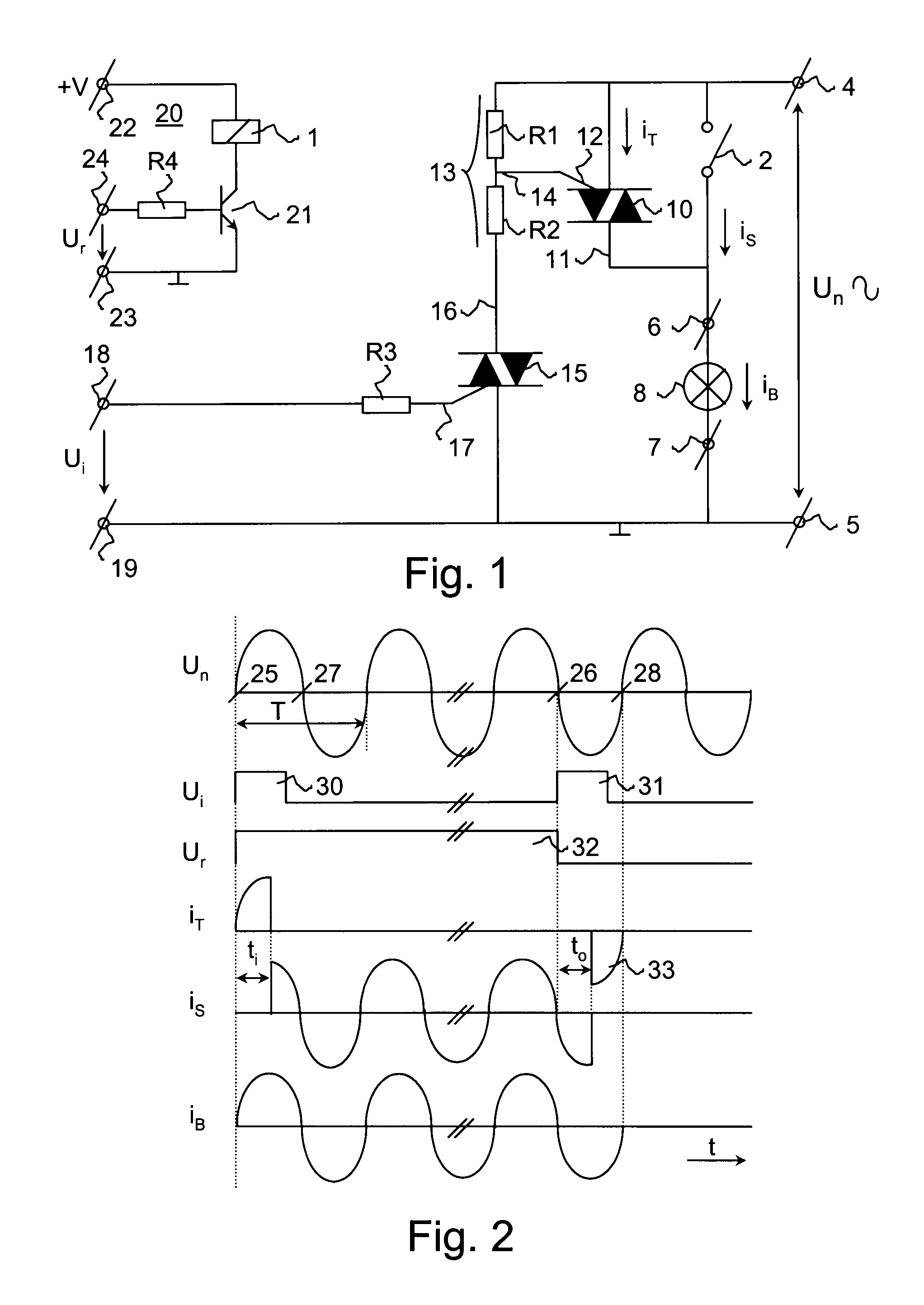
[0045]Numeral 1 indicates the electrical coil of an electromechanical monostable relay comprising a mechanical switching element 2. The mechanical switching element 2 comprises a stable position, this is the position of the switching element 2 in the non-conducting state, i.e. the switched-off state thereof. The switching element 2 is brought in its conducting state, i.e. switched on, by energizing the coil 1. In the switched-on state of the switching element 2, a current circuit is closed from a first supply terminal 4 to a second supply terminal 5, via intermediate load terminals 6 and 7 and a load 8 connected between the load terminals, which is shown in the form of a lighting element in the diagram by way of example. Those skilled in t...


PUM


Abstract

The invention relates to a hybrid electrical switching device, comprising an electromechanical relay including a mechanical switching element to be operated by an electrical coil, and a main semiconductor switching element including a control input and a current conduction path which is connected in parallel with the mechanical switching element for energizing an electric load. The main semiconductor switching element is of the type that ceases to conduct when a current through the current conduction path thereof drops below a threshold value. The circuit furthermore comprises an auxiliary semiconductor switching element including a control input and a current conduction path which is connected for controlling the main semiconductor switching element.

Description

CROSS-REFERENCE TO RELATED APPLICATIONS[0001]This application is a Continuation of and claims the benefit of priority under 35 U.S.C. §120 from U.S. Ser. No. 10 / 433,462 filed Nov. 24, 2003, which is the National stage of PCT / NL01 / 00881 filed Dec. 4, 2001, which claims priority under 35 U.S.C. §119 from Netherlands Application No. 1016791 filed Dec. 4, 2000, the entire contents of each of which are incorporated herein by reference.STATEMENT REGARDING FEDERALLY SPONSORED RESEARCH OR DEVELOPMENT[0002]Not applicableTHE NAMES OF THE PARTIES TO A JOINT RESEARCH AGREEMENT[0003]Not applicableINCORPORATION-BY-REFERENCE OF MATERIAL SUBMITTED ON A COMPACT DISC or REFERENCE TO A “MICROFICHE APPENDIX”[0004]Not applicableBACKGROUND OF THE INVENTION[0005]1. Field of the Invention[0006]The invention relates to a hybrid electrical switching device, comprising an electromechanical relay with a by means of an electrical coil operational mechanical switching element and a main semiconductor switching e...

Claims


Application Information

Patent Timeline
Patent Type & Authority Applications(United States)
IPC IPC(8): H01H47/00H01H51/34H01H9/54
CPCH01H9/542
Inventor SCHASFOORT, PETRUS JOHANNES PLECHELMUS
Owner EATON ELECTRIC INC
Why Eureka
Try Eureka