Video surveillance system and method

a video surveillance and video technology, applied in the field of transmission equipment, can solve the problem of limited distance between the power supply and the camera

Inactive Publication Date: 2008-06-05
PORTA SYST
View PDF6 Cites 2 Cited by
  • Summary
  • Abstract
  • Description
  • Claims
  • Application Information

AI Technical Summary

Benefits of technology

[0008]It is an object of the present invention to provide a system and method for powering remotely-located electron

Problems solved by technology

The disadvantage of the current art described above is that the distance between the power supply and the camera is limited due to the vo

Method used


Image

  • Video surveillance system and method
  • Video surveillance system and method
  • Video surveillance system and method

Examples


Embodiment Construction

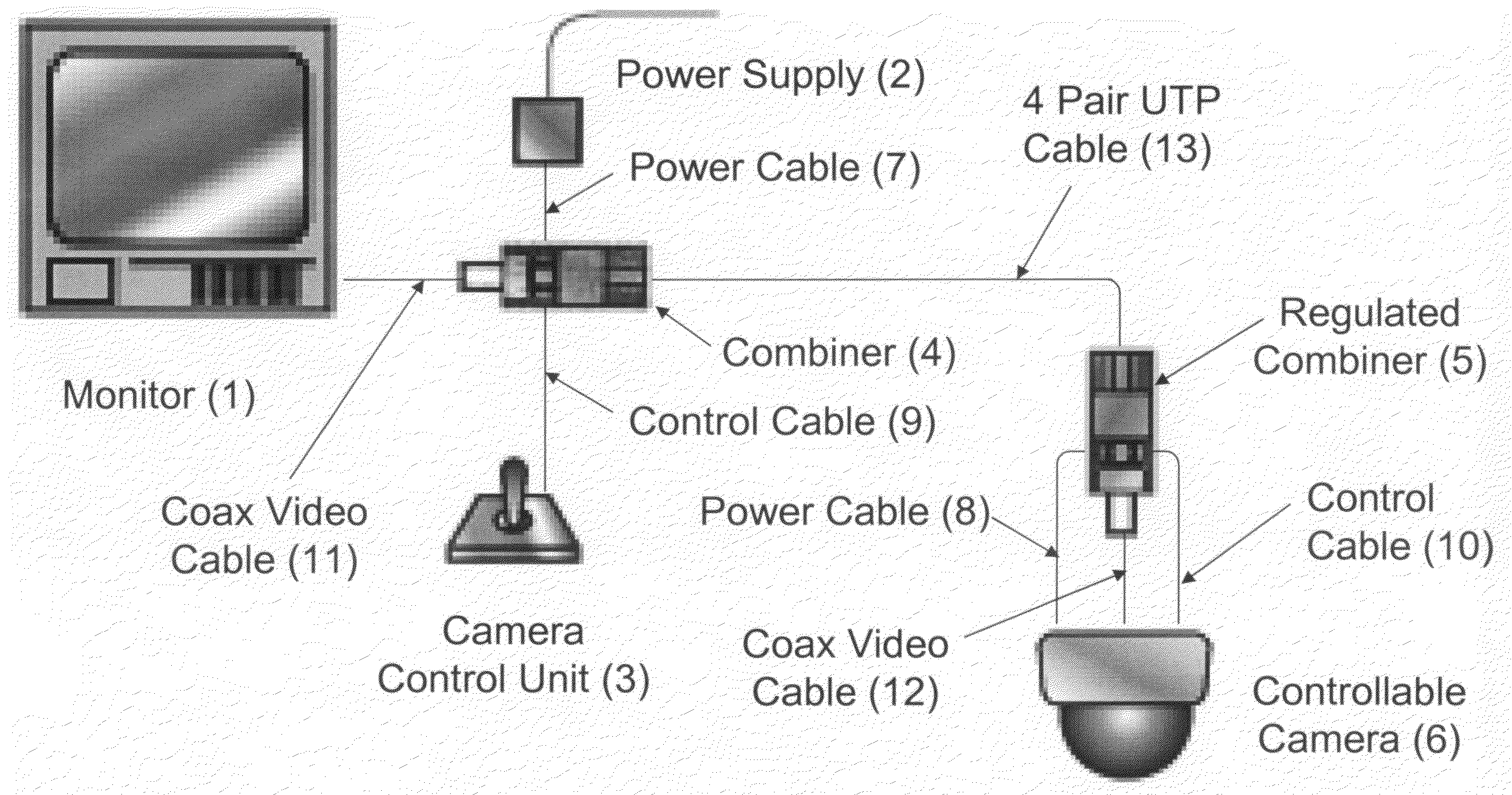
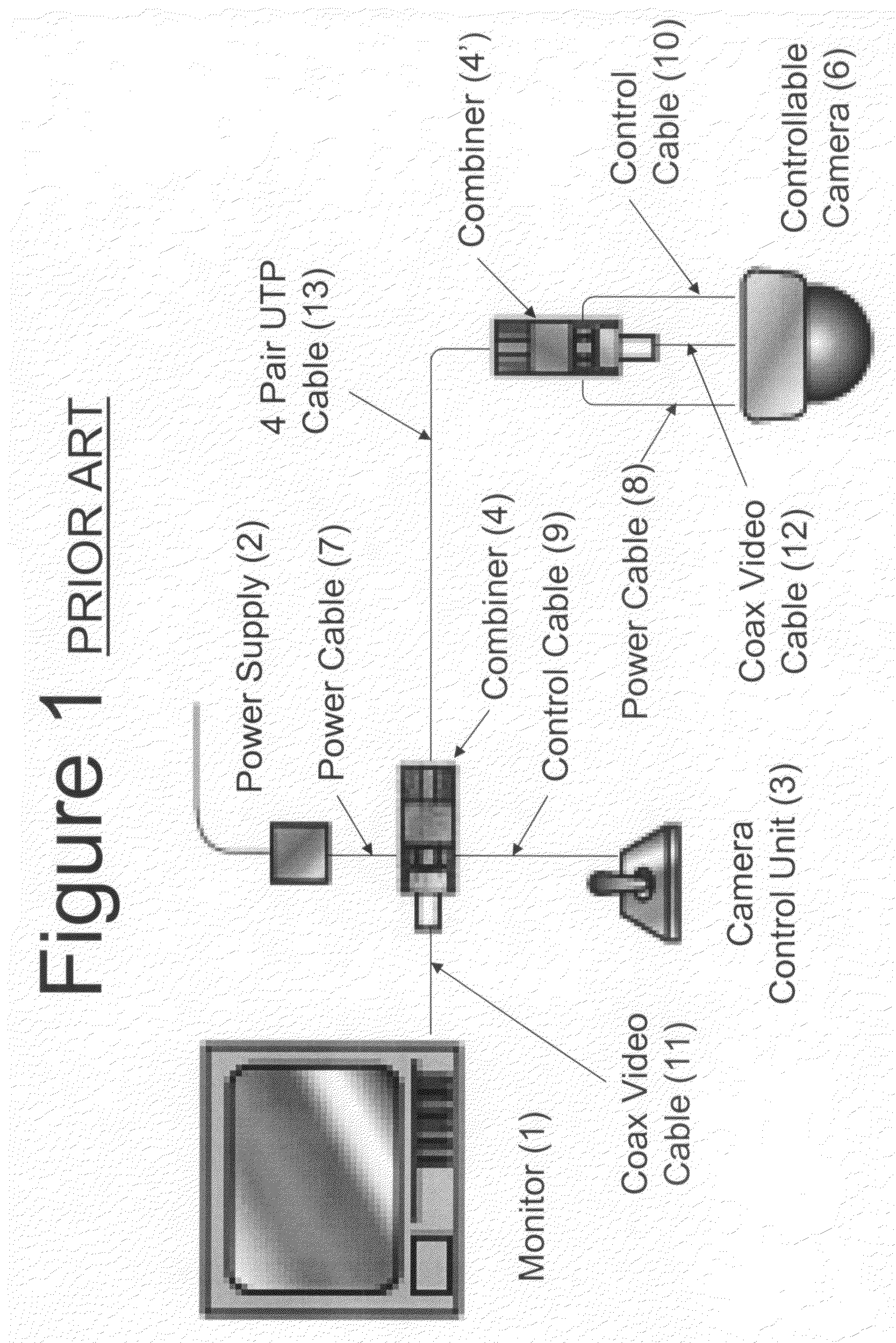
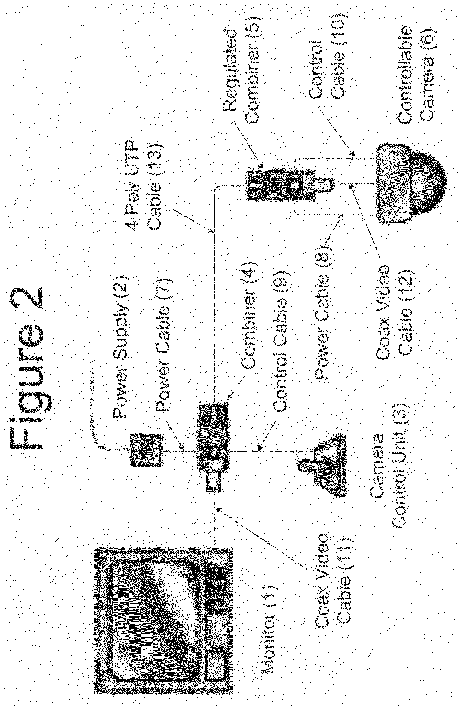
[0025]The method used for this invention is an improvement to the current state of the art shown in the system block diagram of FIG. 1. As shown in FIG. 1, the monitor (1) of the conventional surveillance system is connected to the combiner (4) using a coax cable (11). The power supply (2) is connected to the combiner (4) using a power cable (7) or hookup wires. The camera control unit (3) is connected to the first combiner (4) using control cable (9) or hookup wires. The combiner is then connected to a cable (13) which connects to the other combiner (4′) which is located close to the camera (6). The cable (13) is typically a four pair UTP cable meeting the category 5, 5e, or 6 performance specifications, but the cable may be any other suitable cable. The second combiner (4′) is identical to the first combiner (4) in the current state of the art. Exiting the second combiner (4′) are the power cable (8), the control cable (10), and the coaxial video cable (12).

[0026]Referring now to ...


PUM


Abstract

A video surveillance system includes a first combiner, and a monitor, a power source and a camera control unit, each of which is electrically coupled to the first combiner. A regulated combiner located remotely from the first combiner and being electrically connected to the first combiner with at least one twisted pair of wires includes a voltage regulator which provides a regulated voltage to the camera located remotely from the first combiner. The camera is operable at a predetermined voltage level. The power supply provides an increased voltage to the regulated combiner through the first combiner and the twisted pair of wires to compensate for IR losses in the twisted pair of wires. Thus, the regulated combiner reduces the increased voltage to a safe level for the CCTV camera and other devices on a network to operate properly. The system dramatically increases the distance that a power supply can be located from where the camera is located, which decreases installation costs for CCTV surveillance systems.

Description

CROSS REFERENCE TO RELATED APPLICATION[0001]This application is related to U.S. Provisional Application Ser. No. 60 / 851,169 filed on Oct. 12, 2006, and entitled “Regulated Combiner”, the disclosure of which is incorporated herein by reference and on which priority is hereby claimed.BACKGROUND OF THE INVENTION[0002]1. Field of the Invention[0003]This invention relates to transmission equipment for CCTV (closed circuit television) surveillance applications.[0004]2. Description of the Prior Art[0005]There are various solutions for supplying power and control to remote CCTV cameras while transmitting video to receiving, displaying, and or recording equipment which can include VCR's, DVR's, multiplexers, and monitors. One typical configuration of a video surveillance system is to locate a joystick for camera control, a power supply for the camera, and a monitor in close proximity to each other. The camera which transmits video back to the monitor is located away from the other equipment....

Claims


Application Information

Patent Timeline
IPC IPC(8): H04N7/18
CPCH04N7/183
Inventor SQUILLANTE, ALAN J.KOBSA, PETERMILLER, CHRISTOPHER J.
Owner PORTA SYST
Why Eureka
Try Eureka